One diode, resistive load
Chapter 2 is rectifiers: ac of fixed magnitude and frequency (50, 60 or 400 Hz) in, dc out, with solid-state devices and no rotating machine (slide 2). A diode rectifier gives a fixed dc output, because nobody tells a diode when to turn on. An SCR rectifier gives an adjustable one, because you choose when each thyristor fires. That comes later.
$V_s$ is an rms value. The source is $v_s = \sqrt{2}V_s\sin\omega t$, so its peak is $\sqrt{2}V_s$. Dr. Xu wrote "$V_s$: RMS value" twice on slide 3, with the definition $\sqrt{\frac{1}{T}\int_0^T v^2\,dt}$. A 120 V outlet peaks at 170 V.
- Assume it is off: $i_D = 0$, so the load drops nothing and KVL, $v_s = v_D + v_o$, gives $v_D = v_s$.
- $v_D > 0$ means the assumption was wrong: the diode is on. Replace it with a short ($V_{D,ON} = 0$), so $v_o = v_s$ and $i_s = v_s/R$.
- It turns off when its current falls to zero ($i_D \to 0$); after that $v_D < 0$. Watch the current, not the voltage. With a resistor both happen together at $\pi$. With an inductor they don't (section 02).
Resistive load, one cycle. The diode conducts from 0 to $\pi$ (conduction angle $\theta = 180^\circ$), then blocks $v_D = v_s$, down to $-\sqrt{2}V_s$ at $3\pi/2$.
Average output voltage (slide 3)
- Average = area over one period. In angle, $T = 2\pi$, and $v_o = v_s$ only from 0 to $\pi$: $$V_{o,avg} = \frac{\text{Area } A_1}{T} = \frac{1}{2\pi}\int_0^{\pi}\sqrt{2}V_s\sin(\omega t)\,d\omega t$$
- $$= \frac{\sqrt{2}V_s}{2\pi}\Big[-\cos(\omega t)\Big]_0^{\pi} = \frac{\sqrt{2}V_s}{2\pi}\big(1 - (-1)\big) = \frac{\sqrt{2}V_s}{2\pi}\cdot 2$$ The step the slide skips: $-\cos\pi = +1$ and $+\cos 0 = +1$, so the bracket is 2.
- $$\boxed{V_{o,avg} = \frac{\sqrt{2}}{\pi}V_s = 0.45V_s}$$ Dr. Xu circled the 0.45 and labelled $V_{o,avg}$ "DC side". Not on your formula sheet.
During $\pi < \omega t < 2\pi$, what is the voltage across the diode?
Off means $i_s = 0$, so $v_R = 0$ and KVL gives $v_D = v_s - v_o = v_s$. Here $v_s < 0$, so $v_D < 0$: reverse biased, which confirms "off". The worst moment is $3\pi/2$, where the diode blocks $\sqrt{2}V_s$. That peak is the reverse voltage rating you buy the diode for.
Add an inductor: the diode stays on past $\pi$
Put L in series with R (Dr. Xu: "RL load"). An inductor's current can't jump. When $v_s$ crosses zero at $\pi$, current is still flowing, so the diode stays on and $v_o$ follows $v_s$ below zero. It lets go only when L has given back all its energy and $i_s$ reaches zero, at an angle $\theta > 180^\circ$. Step through slide 5's four periods.
My example, not from the slides: $V_s = 120$ V, 60 Hz, $R = 10\ \Omega$, $\omega L = 10\ \Omega$. It conducts until $\theta = 225.8^\circ$. The current peaks at $\theta_1 = 130.9^\circ$, where $v_s = v_R$, so $v_L = 0$.
Two questions to ask every time: (1) how do you know the diode is off, and (2) KVL, $v_s = v_D + v_o$, with $v_o = v_s$ when it's on and 0 when it's off. Dr. Xu marked the rising $i_s$ "charge", the falling part "discharge", the top "peak", and the end "fully discharged, $i_D = 0$". Only there does $v_D$ drop below zero.
Average output voltage (slide 4)
- $v_o = v_s$ for the whole conduction interval, 0 to $\theta$, including the negative piece from $\pi$ to $\theta$: $$V_{o,avg} = \frac{\text{Area } A_1 - \text{Area } A_2}{T} = \frac{1}{2\pi}\int_0^{\theta}\sqrt{2}V_s\sin(\omega t)\,d\omega t$$ Dr. Xu circled the upper limit: $\theta$, "not $\pi$". One integral to $\theta$ subtracts $A_2$ by itself, because the sine is negative past $\pi$.
- $$= \frac{\sqrt{2}V_s}{2\pi}\Big[-\cos(\omega t)\Big]_0^{\theta} \;\Rightarrow\; \boxed{V_{o,avg} = \frac{\sqrt{2}}{2\pi}V_s(1 - \cos\theta)}$$ Check: $\theta = \pi$ gives $0.45V_s$ again. Any $\theta > 180^\circ$ makes $1 - \cos\theta < 2$, so the inductor lowers the average. In the example, $\theta = 225.8^\circ$ gives 45.84 V instead of 54.02 V. Not on your formula sheet.
- And $\theta$ itself? Dr. Xu's red note: "$\theta$: no formula". It is where the RL current returns to zero, an equation with a sine and an exponential in it. You get it by trial and error or simulation, then use the formula above. An exam would give you $\theta$, or ask which way it moves.
Extra if you have time: where "no formula" comes from
While the diode conducts, KVL is $\sqrt{2}V_s\sin\omega t = Ri_s + L\,di_s/dt$ with $i_s(0) = 0$. A forced (phasor) part plus a decaying part: $$i_s(\omega t) = \frac{\sqrt{2}V_s}{Z}\left[\sin(\omega t - \varphi) + \sin\varphi\,e^{-\omega t/(\omega L/R)}\right],\quad Z = \sqrt{R^2 + (\omega L)^2},\ \varphi = \tan^{-1}\frac{\omega L}{R}$$
Setting $i_s(\theta) = 0$ traps $\theta$ inside a sine and an exponential, so no algebra isolates it. In the example, $\varphi = 45^\circ$ and the bracket's amplitude is 12.0 A; trials at $225^\circ$ (+0.167 A) and $226^\circ$ (−0.045 A) bracket $\theta = 225.8^\circ$. The exponent needs radians.
You add an inductor in series with the resistor of a half-wave rectifier. What happens to $\theta$ and to $V_{o,avg}$?
L keeps the diode on into the negative half cycle, so $v_o$ picks up the negative area $A_2$ and $V_{o,avg} = \frac{\sqrt{2}}{2\pi}V_s(1-\cos\theta)$ falls below $0.45V_s$. "L has no average voltage" is true, and it is exactly why $I_{o,avg} = V_{o,avg}/R$ falls too.
Harmonics, THD and power factor
Zoom out. A sinusoidal ac source, in steady state (both are Dr. Xu's margin notes), feeds a nonlinear circuit such as a rectifier. The voltage stays a sine wave; the current doesn't. Slide 6 sketches the typical culprit: narrow pulses near the voltage peaks. Fourier splits that current into sines:
$$i_s = \sqrt{2}I_{s1}\sin(\omega t + \varphi_1) + \sqrt{2}I_{s2}\sin(2\omega t + \varphi_2) + \sqrt{2}I_{s3}\sin(3\omega t + \varphi_3) + \dots$$Each $I_{sk}$ is an rms value, which is why every term carries $\sqrt{2}$ (circled in class). Different frequencies are orthogonal, so their cross terms average to zero and rms values add in squares: $I_s = \sqrt{I_{s1}^2 + I_{s2}^2 + I_{s3}^2 + \dots}$. Total harmonic distortion compares everything that isn't the fundamental with the fundamental: $$\text{THD} = \frac{\sqrt{I_s^2 - I_{s1}^2}}{I_{s1}} = \frac{\sqrt{I_{s2}^2 + I_{s3}^2 + \dots}}{I_{s1}}$$
Which current does the work? (slide 7)
- Average power with $v_s = \sqrt{2}V_s\sin\omega t$: $$P = \frac{1}{2\pi}\int_0^{2\pi}\sqrt{2}V_s\sin(\omega t)\left[\sum_{k=1}^{\infty}\sqrt{2}I_{sk}\sin(k\omega t + \varphi_k)\right]d\omega t$$
- The step the slide skips. Product to sum: $$\sin(\omega t)\sin(k\omega t + \varphi_k) = \tfrac{1}{2}\big[\cos((k-1)\omega t + \varphi_k) - \cos((k+1)\omega t + \varphi_k)\big]$$ For $k \ge 2$ both cosines run through whole cycles in $2\pi$, so they integrate to zero.
- Only $k = 1$ survives, and its first cosine is the constant $\cos\varphi_1$: $$P = \frac{1}{2\pi}\cdot 2V_sI_{s1}\cdot\tfrac{1}{2}\cos\varphi_1\cdot 2\pi$$
- $$\boxed{P = V_sI_{s1}\cos\varphi_1}\qquad\boxed{S = V_sI_s}\ \text{(rms values)}$$ Class notes: P is "real power" in W, kW, MW, and only $I_{s1}$ contributes to it. S is the "total capacity" in VA, kVA, MVA. "Harmonic currents occupy capacity" and cause extra losses in lines and transformers. Neither P nor S is on your formula sheet.
Power factor (slide 8)
- $$\text{PF} = \frac{P}{S} = \frac{V_sI_{s1}\cos\varphi_1}{V_sI_s} = \frac{I_{s1}}{I_s}\cos\varphi_1 = \text{DF}\cdot\text{DPF}$$ DPF $= \cos\varphi_1$, the displacement power factor, uses the angle between $v_s$ and the fundamental current (Dr. Xu wrote "fundamental" over $I_{s1}$). DF $= I_{s1}/I_s \le 1$ is the distortion factor.
- Square the THD definition: $$\text{THD}^2 = \frac{I_s^2}{I_{s1}^2} - 1 \;\Rightarrow\; \frac{I_{s1}}{I_s} = \frac{1}{\sqrt{1 + \text{THD}^2}}$$ Class note: THD down means $I_{s1}/I_s$ up, so DF up.
- $$\boxed{\text{PF} = \frac{1}{\sqrt{1 + \text{THD}^2}}\cos\varphi_1}$$ DF, THD and both PF forms are on page 2 of your formula sheet, under "Power Factor, THD and distortion factor".
"DF, THD or crest factor (CF)". CF $= I_{s,peak}/I_s$: 1 for a square wave, 1.41 for a sine, about 3 for a capacitor-input rectifier (Mohan 3-2-4).
- Get $I_s$ (total rms) and $I_{s1}$ (fundamental rms: a peak from a Fourier series must be divided by $\sqrt{2}$).
- THD $= \sqrt{I_s^2 - I_{s1}^2}/I_{s1}$. Divide by $I_{s1}$, not $I_s$.
- DF $= I_{s1}/I_s$ and DPF $= \cos\varphi_1$, the angle of the fundamental only.
- PF $=$ DF $\cdot$ DPF. Check: $P = V_sI_{s1}\,\text{DPF}$ must equal the power the load takes.
Slide 6 writes $\sin(\omega t + \varphi_1)$, so a positive $\varphi_1$ there means the current leads. Mohan (eq. 3-31) writes $\sin(\omega t - \varphi_1)$, where positive means it lags. DPF $= \cos\varphi_1$ is the same either way. On the exam, give the angle and say "lagging" or "leading" in words.
A rectifier draws $I_s = 10$ A rms. Its fundamental is $I_{s1} = 8$ A rms, lagging $v_s$ by $30^\circ$. THD and PF?
$\text{THD} = \frac{\sqrt{10^2 - 8^2}}{8} = \frac{6}{8} = 75\%$. Dividing by $I_s$ instead gives the wrong 60%. DF $= 8/10 = 0.8$, DPF $= \cos 30^\circ = 0.866$, PF $= 0.8\times 0.866 = 0.693$. Other form: $0.866/\sqrt{1 + 0.75^2} = 0.693$. PF $= 0.866$ ignores the distortion; PF $= 0.80$ ignores the phase shift.
Single-phase bridge: a square-wave line current
Four diodes let both half cycles reach the load the same way round. Dr. Xu's margin: the load can be R, RL or capacitive (RC). Flip the source polarity and watch which pair conducts; switch the load between slide 9's R and slide 10's large L.
Dr. Xu's reasoning from class: for $v_s \ge 0$, $v_{D1}, v_{D2} \ge 0$, so $D_1$ and $D_2$ turn on, while $v_{D3}, v_{D4} < 0$ keep $D_3$ and $D_4$ off. For $v_s < 0$ they swap. Either way the load sees $v_d = |v_s|$, and each diode conducts $180^\circ$.
- $v_d = |v_s|$ repeats every $\pi$, so average one hump: $$V_d = \frac{\text{Area } A_1 + \text{Area } A_2}{T} = \frac{1}{\pi}\int_0^{\pi}\sqrt{2}V_s\sin(\omega t)\,d\omega t$$
- $$= \frac{\sqrt{2}V_s}{\pi}\cdot 2 = \boxed{\frac{2\sqrt{2}}{\pi}V_s = 0.90V_s}$$ Twice the single diode's value. On your formula sheet (single-phase, inductive load), and it holds for an R load too.
With a pure R the line current is $i_s = v_s/R$ in both halves: a sine in phase with $v_s$, PF = 1. The distortion comes from the load. Slide 10's second assumption: L is very large, so $i_d$ is constant ("constant current", in red). Replace the load by a current source $I_d$. Dr. Xu sketched the real $i_d$ with a small ripple; the formulas use the flat one.
- The diodes still switch at the zero crossings, so $v_d = |v_s|$ and $V_d = 0.90V_s$ is unchanged.
- $i_s = +I_d$ while $D_1$, $D_2$ conduct and $-I_d$ while $D_3$, $D_4$ do: a square wave in phase with $v_s$. Its Fourier series (slide 11): $$i_s = \frac{4}{\pi}I_d\left(\sin\omega t + \frac{1}{3}\sin 3\omega t + \frac{1}{5}\sin 5\omega t + \dots\right)$$ The skipped step: $b_k = \frac{2}{\pi}\int_0^{\pi}I_d\sin k\omega t\,d\omega t = \frac{2I_d}{k\pi}(1 - \cos k\pi)$, which is $\frac{4I_d}{k\pi}$ for odd $k$ and 0 for even $k$. Class note: "3rd, 5th, 7th: odd order harmonics. AC: no even order."
- The fundamental's peak is $I_{s1,peak} = \frac{4}{\pi}I_d$, so its rms is $$I_{s1} = \frac{4}{\sqrt{2}\,\pi}I_d = \frac{2\sqrt{2}}{\pi}I_d = 0.9I_d$$ and the total rms is $I_s = \sqrt{\frac{1}{T}\int_0^T I_d^2\,dt} = I_d$, because $i_s^2 = I_d^2$ at every instant (slide 12).
- $$\text{THD} = \frac{\sqrt{I_d^2 - \frac{8}{\pi^2}I_d^2}}{\frac{2\sqrt{2}}{\pi}I_d} = \sqrt{\frac{\pi^2}{8} - 1} = 0.4834$$ $I_d$ cancels: every square wave has 48.34% THD, whatever its height.
- $i_{s1}$ is in phase with $v_s$, so $\varphi_1 = 0$ and DPF $= \cos 0^\circ = 1$. DF $= \frac{I_{s1}}{I_s} = \frac{2\sqrt{2}}{\pi} = 0.9$, so $$\boxed{\text{PF} = \text{DF}\cdot\text{DPF} = 0.9}$$
$P_{in} = V_sI_{s1}\,\text{DPF} = V_s(0.9I_d)(1) = 0.9V_sI_d$, and $P_{out} = V_dI_d = 0.9V_sI_d$. Equal, as they must be with ideal diodes. You can also write $P_{in} = V_sI_s\,\text{PF}$: same number. But $S = V_sI_s = V_sI_d$ is 11% bigger than the power delivered, and that extra VA is the harmonics.
"Single phase diode rectifier with inductive load": $V_d = 0.90V_s$, $I_{s,rms} = I_d$, and the $i_s(t)$ series. Not on it: $I_{s1} = 0.9I_d$ (read the peak $\frac{4}{\pi}I_d$ off the series, divide by $\sqrt{2}$), DPF = 1, DF = 0.9, THD = 48.3%, PF = 0.9.
A single-phase bridge feeds a large inductor carrying $I_d = 10$ A. What is $I_{s1}$, the rms of the fundamental line current?
$\frac{4}{\pi}I_d = 12.73$ A is the fundamental's peak; divide by $\sqrt{2}$ for rms: $\frac{2\sqrt{2}}{\pi}\times 10 = 9.0$ A. 10 A is the rms of the whole square wave ($I_s$), and 6.37 A is $\frac{2}{\pi}I_d$, which isn't anything here.
Three-phase bridge: a six-step line current
The Oct 6 slides stop at slide 12, single-phase. The three-phase bridge is on your F2026 formula sheet (page 2, right-hand column) and in the F2025 final (Q3), so it is taught here from the sheet and Mohan 5-6-1. If the Oct 13 lecture covers it, check the notation against those slides.
Six diodes: $D_1$, $D_3$, $D_5$ on top and $D_4$, $D_6$, $D_2$ below. With $I_d$ flowing, the top diode whose anode sees the highest phase voltage conducts, and the bottom diode whose cathode sees the lowest. So $v_d$ is always the largest line-to-line voltage: six humps per cycle, a "six-pulse" rectifier.
480 V line-to-line, $I_d = 100$ A. Top: the six line-to-line voltages (faint) and $v_d$, their top envelope. Bottom: $i_a$ with its fundamental, and $v_{an}$ (dashed) for phase.
- Each hump of $v_d$ is the slice of a line-to-line sine, peak $\sqrt{2}V_{LL}$, from $60^\circ$ to $120^\circ$, and the pattern repeats every $\pi/3$.
- $$V_{d,avg} = \frac{1}{\pi/3}\int_{\pi/3}^{2\pi/3}\sqrt{2}V_{LL}\sin\theta\,d\theta = \frac{3}{\pi}\sqrt{2}V_{LL}\left(\tfrac{1}{2} + \tfrac{1}{2}\right) = \boxed{\frac{3\sqrt{2}}{\pi}V_{LL} = 1.35V_{LL}}$$ $V_{LL}$ is the rms line-to-line voltage. On the sheet.
- Each diode conducts $120^\circ$. Phase a: $D_1$ carries $+I_d$ while $v_{an}$ is highest ($30^\circ$ to $150^\circ$), $D_4$ carries $-I_d$ while it is lowest ($210^\circ$ to $330^\circ$), and $i_a = 0$ in the two $60^\circ$ gaps. The rms sees $I_d^2$ for $240^\circ$ of $360^\circ$: $$I_{a,rms} = \sqrt{\tfrac{2}{3}}\,I_d = 0.816I_d\quad\text{(on the sheet)}$$
- From the sheet's series, $$i_a = \frac{2\sqrt{3}}{\pi}I_d\left[\sin\omega t - \frac{1}{5}\sin 5\omega t - \frac{1}{7}\sin 7\omega t + \dots\right]$$ the fundamental's peak is $\frac{2\sqrt{3}}{\pi}I_d$, so its rms is $$I_{a1} = \frac{2\sqrt{3}}{\sqrt{2}\,\pi}I_d = \frac{\sqrt{6}}{\pi}I_d = 0.780I_d$$ Not on the sheet. Same move as single phase: peak off the series, divide by $\sqrt{2}$.
- DF $= \frac{I_{a1}}{I_{a,rms}} = \frac{\sqrt{6}/\pi}{\sqrt{2/3}} = \frac{3}{\pi} = 0.955$. $i_{a1}$ is centred on the peak of $v_{an}$, so DPF = 1 and $$\boxed{\text{PF} = \frac{3}{\pi} = 0.955},\qquad \text{THD} = \sqrt{\frac{\pi^2}{9} - 1} = 31.1\%$$
- Harmonics: no even ones (half-wave symmetry) and no multiples of 3 (the $60^\circ$ gaps cancel them). Only $h = 6n \pm 1$: 5, 7, 11, 13, ..., each $I_{ah} = I_{a1}/h$. Better than single phase on every count: PF 0.955 against 0.9, THD 31% against 48%, and the dc ripple at six times line frequency instead of two.
"Three phase diode rectifier with inductive load": $V_{d,avg} = 1.35V_{LL}$, $I_{a,rms} = 0.816I_d$, and the $i_a(t)$ series. Not on it: $I_{a1} = \frac{\sqrt{6}}{\pi}I_d = 0.780I_d$, DF = PF = $3/\pi$ = 0.955, THD = 31.1%, $h = 6n \pm 1$. Power check: $P = \sqrt{3}V_{LL}I_{a1}\,\text{DPF} = V_dI_d$.
A three-phase diode bridge carries $I_d = 100$ A. What is $I_{a1}$, the rms of the fundamental line current?
$I_{a1} = \frac{\sqrt{6}}{\pi}\times 100 = 78.0$ A. 81.6 A is $I_{a,rms}$, the whole six-step wave, straight off the sheet. 110.3 A is the fundamental's peak, $\frac{2\sqrt{3}}{\pi}I_d$. 90.0 A is the single-phase answer, $0.9I_d$. Then DF $= 78.0/81.6 = 0.955$.
Rectifier bench: single or three phase
Ideal diodes, no line inductance, and a load inductor big enough to hold $i_d = I_d$. Pick the supply, set the voltage and $I_d$, and every readout comes from the formulas above, so it doubles as an answer checker. Flip between single and three phase with the same numbers and watch THD and PF move.
Capacitive load Preview
The Oct 6 deck stops at slide 12. The capacitive-load rectifier is on your F2026 formula sheet (last box of page 2) and was F2025 midterm Q3, worth 25%. It may be taught in the Oct 13 lecture; when those slides come out, check the notation ($\theta_b$, $\theta_p$, $\theta_f$, $L_s$, $V_d$) against them. This section is built from the sheet, the posted solution and Mohan 5-3-3.
Phone chargers, PCs and LED drivers put a big capacitor right after the bridge. In the exam's Figure 3a the source feeds the bridge through $L_s$ (line plus transformer inductance), and C holds the dc side at a nearly constant $V_d$.
- Start. The capacitor holds the bridge output at $V_d$, so $D_1$, $D_2$ stay reverse biased until $v_s$ climbs to $V_d$: $$\sqrt{2}V_s\sin\theta_b = V_d \;\Rightarrow\; \theta_b = \arcsin\frac{V_d}{\sqrt{2}V_s}$$
- While they conduct, KVL around source, $L_s$ and capacitor gives $L_s\frac{di_d}{dt} = \sqrt{2}V_s\sin\omega t - V_d$. With $\theta = \omega t$, $dt = d\theta/\omega$: $$\omega L_s\frac{di_d}{d\theta} = \sqrt{2}V_s\sin\theta - V_d$$
- Integrate from $\theta_b$, where $i_d = 0$: $$\boxed{i_d = \frac{1}{\omega L_s}\Big[\sqrt{2}V_s(-\cos\theta + \cos\theta_b) - V_d(\theta - \theta_b)\Big]}$$ The formula-sheet line. $\theta - \theta_b$ came from integrating $d\theta$, so it must be in radians.
- Peak. $di_d/d\theta = 0$ where $v_s$ falls back to $V_d$. By the symmetry of the sine, $$\theta_p = \pi - \theta_b$$ The current peaks after the voltage peak: it keeps rising as long as $v_s - V_d > 0$.
- End. After $\theta_p$ the current falls, but the diodes stay on until it reaches zero at $\theta_f$: $$i_d(\theta_f) = 0 \iff \int_{\theta_b}^{\theta_f}\big(\sqrt{2}V_s\sin\theta - V_d\big)\,d\theta = 0$$ The area where $v_s > V_d$ equals the area where $v_s < V_d$ (red and yellow on the bench below). $\theta_f$ sits inside a cosine and on its own, so there is no closed form: trial and error.
- $\theta_b = \arcsin\frac{V_d}{\sqrt{2}V_s}$. Write it in rad and degrees, and check one against the other.
- $\theta_p = \pi - \theta_b$.
- $\omega L_s = 2\pi fL_s$, then $i_{d,peak} = i_d(\theta_p)$. Keep 6 significant figures: it's a small difference of two big numbers.
- $\theta_f$: try angles in $i_d(\theta)$. Positive: still conducting, go later. Negative: overshot, go earlier. Stop when $|i_d|$ is tiny (the solution stopped at 0.0101 A).
- Conduction angle of each diode pair: $\theta_f - \theta_b$.
Why the line current is so bad
The load draws current all the time, but the capacitor can only be refilled between $\theta_b$ and $\theta_f$: $46^\circ$ of every $180^\circ$ in the exam problem. The same charge in a much shorter time comes as a tall, narrow pulse, full of 3rd, 5th and 7th harmonics. For the exam values: THD about 132%, PF about 0.59, crest factor about 3.
Fixing it (the F2025 solution's three methods)
- Passive or active power filter. Add L or LC on the ac side of the rectifier. More inductance makes the pulse lower and wider; an active filter supplies the harmonic currents itself so the line doesn't have to.
- Zig-zag transformer, or a multi-phase rectifier. Phase-shifted windings make the harmonics of different rectifiers cancel, and a zig-zag winding gives the triplen currents a local path that keeps them out of the upstream transformer and neutral.
- Power factor correction (PFC) circuit. An active front end, usually a boost converter right after the bridge (Dr. Xu sketched one on slide 10), forces $i_s$ to follow the shape of $v_s$: THD near 0, PF near 1.
Buildings feed single-phase loads phase to neutral from a three-phase, four-wire system. The fundamentals of the three phases are $120^\circ$ apart and cancel in the neutral. The 3rd harmonics are $3\times 120^\circ = 360^\circ$ apart, so they are in phase and add: the neutral carries about $3I_{s3}$ (Mohan 5-5), even with balanced loads. Every harmonic current also adds copper and core loss in the transformer without delivering power, which is the slide 7 note in action.
Where does $i_d$ reach its peak?
$\omega L_s\,di_d/d\theta = v_s - V_d$ stays positive until $v_s$ drops back to $V_d$, at $\theta_p = \pi - \theta_b$ by the symmetry of the sine, so the current keeps climbing past the voltage peak. The pulse isn't symmetric either: in the exam problem it rises over $30.7^\circ$ and falls over $15.5^\circ$. At $\theta_f$ the current is zero, not at its peak.
In the exam circuit you double $L_s$ and keep $V_d = 150$ V. What happens to the pulse?
$L_s$ only appears in the factor $\frac{1}{\omega L_s}$ in front of the bracket, so it scales the whole curve. $\theta_b$ and $\theta_p$ depend only on $V_d/\sqrt{2}V_s$, and the equal-area condition for $\theta_f$ has no $L_s$ in it. In a real circuit the load keeps drawing its power, so with more $L_s$ the capacitor voltage sags until the pulses deliver enough charge again: lower $V_d$, earlier $\theta_b$, wider pulse, lower THD. That's why "add L" works. Compare the two "Ls × 5" presets on the bench below.
Capacitive rectifier solver
The formula-sheet model: $V_d$ held constant by a large C, ideal diodes, $i_d$ starting from zero at $\theta_b$. $\theta_f$ is found by bisection on $i_d(\theta) = 0$, and the table shows hand trials the way the exam solution wrote them. Switch "Hold" to the load current to let $V_d$ settle the way a real circuit does.
Your sheet: what's there, what isn't
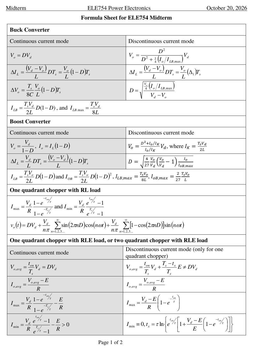
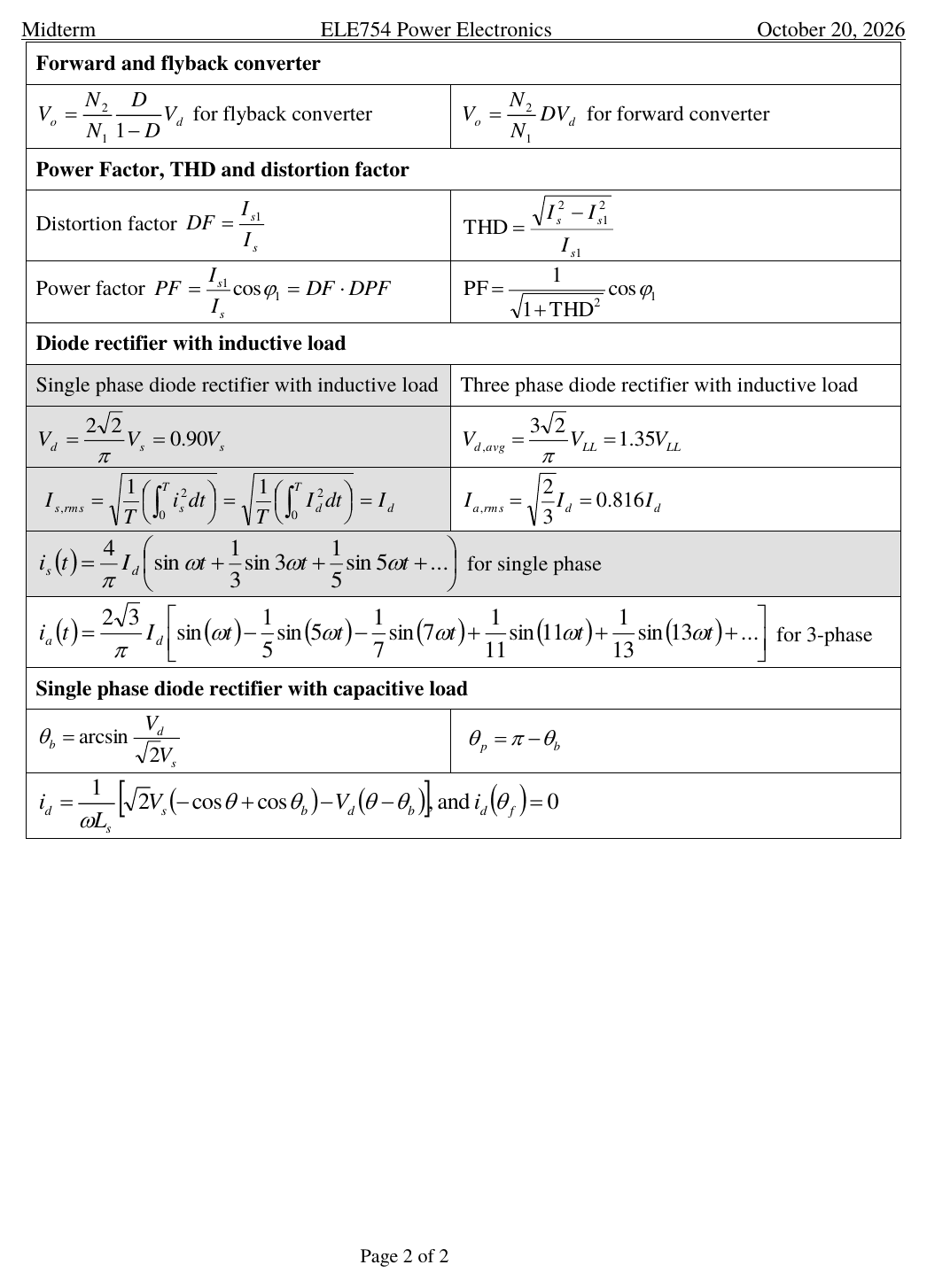
Open it with the button at the top. Everything this lesson takes from the sheet sits in three boxes on page 2. The first list is what you can copy; the second is what you must carry in your head.
On the sheet
- Power Factor, THD and distortion factor: DF $= I_{s1}/I_s$, THD $= \sqrt{I_s^2 - I_{s1}^2}/I_{s1}$, PF $= \frac{I_{s1}}{I_s}\cos\varphi_1 = $ DF $\cdot$ DPF, PF $= \cos\varphi_1/\sqrt{1 + \text{THD}^2}$.
- Single phase, inductive load: $V_d = 0.90V_s$, $I_{s,rms} = I_d$, the $i_s(t)$ series.
- Three phase, inductive load: $V_{d,avg} = 1.35V_{LL}$, $I_{a,rms} = 0.816I_d$, the $i_a(t)$ series.
- Single phase, capacitive load: $\theta_b$, $\theta_p = \pi - \theta_b$, $i_d(\theta)$, and $i_d(\theta_f) = 0$.
Not on the sheet
- Single diode: $0.45V_s$ (R load) and $\frac{\sqrt{2}}{2\pi}V_s(1 - \cos\theta)$ (RL load, $\theta > 180^\circ$ found numerically).
- $P = V_sI_{s1}\cos\varphi_1$, $S = V_sI_s$, and $I_s = \sqrt{I_{s1}^2 + I_{s2}^2 + \dots}$.
- Fundamental rms = peak from the series $\div\sqrt{2}$: $I_{s1} = 0.9I_d$ (single), $I_{a1} = \frac{\sqrt{6}}{\pi}I_d = 0.780I_d$ (three).
- DPF = 1 for both diode bridges; DF = PF = 0.9 (single) and $3/\pi = 0.955$ (three); THD = 48.3% and 31.1%.
- Harmonic orders: odd only (single), $6n \pm 1$ (three), each $I_h = I_1/h$.
- Capacitive load: radians in $V_d(\theta - \theta_b)$, conduction angle $\theta_f - \theta_b$, and the three fixes for harmonics.
F2025 midterm, Question 3 (25%)
Work it like the real thing: (this year's, the one you'll get on Oct 20), try each part on paper in your notes, then reveal.
A single-phase full-bridge diode rectifier with a capacitive load (Figure 3a) is powered by the wall outlet: $v_s$ is 110 V rms, 60 Hz, with a total inductance $L_s = 0.1$ mH. The dc voltage is $V_d = 150$ V. All the diodes are ideal. Refer to the waveform of $i_d$ in Figure 3b.
Figure 3b, redrawn to scale from the solution's numbers.
Try it first. Hint: before $\theta_b$ the capacitor holds the diodes off.
- Conduction starts when $v_s$ reaches $V_d$: $\sqrt{2}V_s\sin\theta_b = V_d$, with $\sqrt{2}V_s = \sqrt{2}\times 110 = 155.56$ V.
- $\theta_b = \arcsin\frac{150}{155.56} = \arcsin(0.9642) = $ 1.3025 rad = 74.63°
The handwritten answer reads "1.3052 rad or 74.63°". Those don't match: $74.63^\circ = 1.3025$ rad, and 1.3052 rad would be $74.78^\circ$. The degrees are right, and part 3.2's $\theta_p = 1.8390$ rad is $\pi - 1.3025$, so every later part used the correct value. On the exam, write both units and check one against the other.
- $i_d$ peaks where $v_s - V_d = 0$ on the falling side of $v_s$.
- $\theta_p = \pi - \theta_b = 3.1416 - 1.3025 = $ 1.8390 rad = 105.37°
- $\omega L_s = 2\pi\times 60\times 0.1\times 10^{-3}$ $= 0.037699\ \Omega$.
- $\cos\theta_b = 0.26504$ and $-\cos\theta_p = +0.26504$ (since $\theta_p = \pi - \theta_b$), so the first term is $155.563\times 0.53009 = 82.4621$ V·rad.
- Second term: $V_d(\theta_p - \theta_b) = 150\times 0.53650 = 80.4746$ V·rad, in radians.
- $$i_{d,peak} = i_d(\theta_p) = \frac{82.4621 - 80.4746}{0.037699} = \frac{1.9875}{0.037699}$$ $i_{d,peak} =$ 52.72 A A small difference of two big numbers: rounded to 82.46 and 80.47, the terms give 52.79 A. Full precision gives 52.7194 A, which matches the solution's handwritten value.
- The posted solution's trials, each reproduced by the formula:
θ (deg) id(θ) (A) read it as 120 6.2513 still positive: go later 122 −9.1773 negative: overshot 120.8 0.3900 close, still positive 120.85 0.0101 tiny: stop - $\theta_f \approx$ 120.85° = 2.1092 rad The exact root is $120.8513^\circ$. Each diode pair conducts $\theta_f - \theta_b = 46.22^\circ$ per half cycle.
- Passive or active power filter: for example, add LC or L on the ac side of the rectifier.
- Zig-zag transformer, or a multi-phase rectifier.
- Power factor correction (PFC) circuit. One explained method earns the marks. Say why it helps: lower, wider pulses (filter), cancelled harmonics (zig-zag, multi-phase), or a sinusoidal input current (PFC).
F2025 final, Question 3, parts 2 and 3 (10%)
A three-phase full-bridge thyristor rectifier drives a 100 kW dc motor through a very large inductance. The ac input is 600 V (line-to-line), 60 Hz; the winding resistance is 0.15 Ω and the back EMF is $E_a = 750$ V. Part 1 (the firing angle) is SCR material from later in the course, so start from what it gives you: $I_d = I_a = P_{out}/E_a = 100\text{ kW}/750\text{ V} = 133.33$ A. With a very large L, $i_d$ is flat, so the line current is the same six-step wave as the diode bridge, only shifted in time.
- Formula sheet, three-phase row: $I_{s,rms} = \sqrt{\tfrac{2}{3}}I_d = 0.8165\times 133.33 = $ 108.87 A
- Not on the sheet: $I_{s1} = \frac{\sqrt{6}}{\pi}I_d = 0.7797\times 133.33 = 103.96$ A.
- $\text{THD} = \frac{\sqrt{108.87^2 - 103.96^2}}{103.96} = $ 0.3108 (31.1%) Same as any six-step current: $\sqrt{\pi^2/9 - 1}$.
- DF $= 103.96/108.87 = 0.955$. With diodes, DPF = 1 and PF would be 0.955. Here the thyristors fire at $\alpha = 18.08^\circ$ (part 1: $V_d = E_a + R_aI_a = 770$ V $= 1.35V_{LL}\cos\alpha$), which delays the fundamental by $\alpha$: DPF $= \cos\alpha = 0.951$, so PF $= 0.955\times 0.951 = $ 0.908 The posted solution writes out $I_{s1}$ and THD but not PF. DPF = $\cos\alpha$ is SCR material; you'll see why after the midterm.
- Check the power books: $\sqrt{3}V_{LL}I_{s1}\cos\alpha$ $= \sqrt{3}\times 600\times 103.96\times 0.951$ $= 102.7$ kW, and $V_dI_d = 770\times 133.33$ is the same 102.7 kW. The 2.7 kW above 100 kW is the winding loss, $0.15\times 133.33^2$.
Extra if you have time: F2025 final, Question 2 (20%), capacitive load with a trapezoidal source
A single-phase diode bridge with line inductance $L_s = 1$ mH feeds a very large filter capacitor at $V_d = 115$ V. The 60 Hz source is a trapezoid: it rises linearly from 0 to 120 V over $0^\circ$ to $60^\circ$, stays at 120 V until $120^\circ$, falls to 0 at $180^\circ$, and mirrors that below zero. The formula sheet's $i_d$ line assumes a sine, so here you integrate the areas directly.
- $\theta_b$: the ramp reaches 115 V at $\theta_b = 60^\circ\times\frac{115}{120} = 57.5^\circ = 1.0036$ rad. By symmetry $\theta_p = \pi - \theta_b = 122.5^\circ = 2.138$ rad.
- $i_{d,pk} = \frac{1}{\omega L_s}\int_{\theta_b}^{\theta_p}(v_s - V_d)\,d\theta$. That area is a trapezoid of height 5 V with parallel sides $\pi/3$ (the flat top) and $\theta_p - \theta_b$: $\frac{[\pi/3 + (\theta_p - \theta_b)]\times 5}{2} = 5.4542$ V·rad.
- $i_{d,pk} = \frac{5.4542}{0.37699} = $ 14.47 A
- After $\theta_p$ the ramp falls at $120\text{ V}/(\pi/3)$, so the negative area is a triangle: $A_2 = \frac{1}{2}\frac{120}{\pi/3}(\theta_f - \theta_p)^2$. Equal areas, $A_2 = A_1 = 5.4542$: $\theta_f - \theta_p = \sqrt{\frac{2\times 5.4542\times\pi/3}{120}} = 0.3085$ rad.
- $\theta_f = 2.4466$ rad ($140.18^\circ$), so the conduction angle is $\theta_f - \theta_b = $ 1.443 rad = 82.68°
- The solution treats the pulse as a triangle: $i_{d,avg} \approx \frac{i_{d,pk}}{2}\cdot\frac{\theta_f - \theta_b}{\pi} = 3.3226$ A, so $P_{in} = P_{out} = V_di_{d,avg} = $ 382.10 W
The solution writes "≈": the triangle is an approximation. After $\theta_p$ the current falls along a parabola that stays near the peak longer than a straight line, so the exact average, $\frac{1}{\pi}\int_{\theta_b}^{\theta_f}i_d\,d\theta$, is 3.56 A and the power is 409 W, about 7% more. On an exam, say which one you're doing; the triangle is what the solution used.
Traps that cost marks
- Using the peak where the formula wants rms. $V_s$ and $V_{LL}$ are rms; $0.45V_s$, $0.90V_s$ and $1.35V_{LL}$ already contain the $\sqrt{2}$.
- Assuming $\theta = 180^\circ$ with an RL load. It's always more, so $V_{o,avg} = \frac{\sqrt{2}}{2\pi}V_s(1 - \cos\theta)$ is below $0.45V_s$.
- Taking the Fourier coefficient as rms. $\frac{4}{\pi}I_d$ and $\frac{2\sqrt{3}}{\pi}I_d$ are peaks: $I_{s1} = 0.9I_d$ and $I_{a1} = 0.780I_d$.
- THD divided by $I_s$. It's divided by $I_{s1}$.
- PF $= \cos\varphi_1$ for a distorted current. That's only DPF; PF $=$ DF $\cdot$ DPF.
- Counting harmonics as power. $P = V_sI_{s1}\cos\varphi_1$ uses only the fundamental; $S = V_sI_s$ uses everything.
- Three-phase with single-phase numbers (0.9, 48%), or $I_{a,rms} = 0.816I_d$ used as the fundamental.
- Degrees in $V_d(\theta - \theta_b)$. That term needs radians; only the cosines care about your calculator's mode.
- Putting $\theta_p$ at $90^\circ$, or ending the pulse at $\theta_p$. The peak is at $\pi - \theta_b$; the pulse ends at $\theta_f$, where the areas balance.
- No units, no marks: the midterm cover says "Marks will be lost if there is no appropriate units." Give angles in rad and degrees.
Drill it in chat
Go back to the chat and say "quiz me on rectifiers". You get one question at a time, and I'll fix exactly where your reasoning breaks.
Then the grill
grill.pierrek.ca · ELE754 sections "L5: Diode rectifiers" (8 questions), "L5: Harmonics, PF & THD" (8), "Preview: capacitive-load rectifier" (5) and "Formula sheet (F2026): find it, use it, know what's missing" (10).