Two-quadrant chopper: let the current reverse
Slide 62, the last slide of the Sept 22 deck, sets it up. Take last week's one-quadrant chopper, put a second switch $T_2$ across the freewheeling diode $D_1$, and a diode $D_2$ across $T_1$. Dr. Xu's class note: that's a half bridge. The output is still only $V_d$ or 0, so $V_o \ge 0$, but the current can now flow either way: bidirectional power flow. With $I_o > 0$ and $V_o > 0$, power goes from $V_d$ into the load, and $T_1$, $D_1$ make it a buck. With $I_o < 0$ and $V_o > 0$, power comes back out of E into $V_d$, and $T_2$, $D_2$ make it a boost (class sketch on slide 63: charge the battery as a buck, discharge it as a boost). Slide 63's uses: battery charge and discharge, fast dynamic braking of a dc motor, and any dc-dc job with power flowing both ways.
Four gate states, one forbidden
| $T_1$ | $T_2$ | Result (class note, slide 63) |
|---|---|---|
| on | on | Short circuit across $V_d$ (shoot-through). Never. |
| on | off | $v_o = V_d$ |
| off | on | $v_o = 0$ |
| off | off | Dead time (lockout): the current picks its own diode |
$T_1$ and $T_2$ get complementary gate signals: one PWM signal, a buffer to $T_1$ and an inverter to $T_2$, each through a dead-time block. A real switch takes time to turn off, so both are held off for a short $\Delta T \ll T_s$ at every transition. The formulas ignore it.
The four intervals (slides 65 and 66)
With $E$ set so the current crosses zero ($V_d = 100$ V, $D = 0.5$, $E = 50$ V, so $I_{o,avg} = 0$), one period has four intervals. The gate decides which position (upper or lower) is on; the sign of $i_o$ decides whether the switch or its diode carries it.
$I_{\max}$ and $I_{\min}$ (slides 64 and 67)
- Upper position on ($T_1$ or $D_2$), $0 \le t < t_{on}$: $$V_d = L\frac{di_o}{dt} + Ri_o + E \;\Rightarrow\; i_o(t) = \frac{V_d - E}{R}\left(1 - e^{-t/\tau}\right) + I_{\min}e^{-t/\tau} \quad (1)$$
- Lower position on ($T_2$ or $D_1$), $t_{on} \le t < T_s$: $$0 = L\frac{di_o}{dt} + Ri_o + E \;\Rightarrow\; i_o(t) = -\frac{E}{R}\left(1 - e^{-(t - t_{on})/\tau}\right) + I_{\max}e^{-(t - t_{on})/\tau} \quad (2)$$ $\tau = L/R$. Nothing changes when $i_o$ crosses zero, because a device is always there to carry either sign. That's why it is always CCM (class note on slide 64).
- Steady state ties the ends together. Write $a = e^{-t_{on}/\tau}$ and $b = e^{-t_{off}/\tau}$, so $ab = e^{-T_s/\tau}$: $$I_{\max} = \frac{V_d - E}{R}(1 - a) + I_{\min}a \quad (3), \qquad I_{\min} = -\frac{E}{R}(1 - b) + I_{\max}b \quad (4)$$
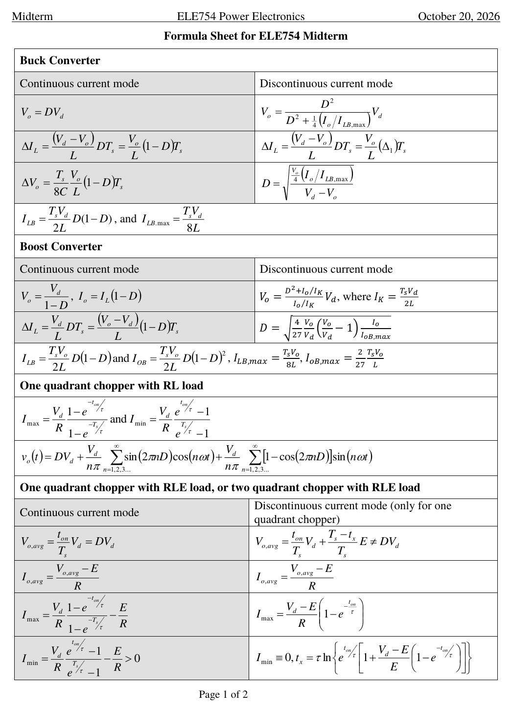
- The algebra slide 67 skips: put (3) into (4) and collect $I_{\min}$: $$I_{\min}(1 - ab) = \frac{V_d}{R}\,b(1 - a) - \frac{E}{R}\big[(1 - b) + b(1 - a)\big] = \frac{V_d}{R}\,b(1 - a) - \frac{E}{R}(1 - ab)$$ Multiply top and bottom by $e^{T_s/\tau}$: $$\boxed{I_{\min} = \frac{V_d}{R}\frac{e^{t_{on}/\tau} - 1}{e^{T_s/\tau} - 1} - \frac{E}{R}}, \qquad \boxed{I_{\max} = \frac{V_d}{R}\frac{1 - e^{-t_{on}/\tau}}{1 - e^{-T_s/\tau}} - \frac{E}{R}}$$ E only shifts the whole current down by $E/R$. The ripple $I_{\max} - I_{\min}$ doesn't depend on E at all.
- Averages: $v_o = V_d$ for $t_{on}$ and 0 for $t_{off}$, with no idle interval, so $$V_{o,avg} = DV_d \text{ always}, \qquad I_{o,avg} = \frac{V_{o,avg} - E}{R} = \frac{DV_d - E}{R}$$ $I_{o,avg} > 0$: power flows into E (motoring). $I_{o,avg} < 0$: E sends power back to $V_d$ (braking, regeneration). Class note on slide 64: $I_o$ is the load current, the dashed average.
The F2026 sheet's row is "One quadrant chopper with RLE load, or two quadrant chopper with RLE load". Its CCM column ends the $I_{\min}$ formula with "$> 0$". That is the CCM test for the one-quadrant chopper. For the two-quadrant chopper use the same formulas even when $I_{\min}$ comes out negative (slide 67: always CCM), and never the DCM column, which the sheet itself labels "only for one quadrant chopper".
A two-quadrant chopper with an RLE load: $V_d = 200$ V, $D = 0.45$, $R = 0.5\ \Omega$, $E = 95$ V. The sheet's CCM formula gives a negative $I_{\min}$. What now?
$T_2$ and $D_2$ carry the negative current, so it never sticks at zero: always CCM, and $V_{o,avg} = DV_d = 90$ V exactly. $I_{o,avg} = (90 - 95)/0.5 = -10$ A. Negative average current with positive voltage is quadrant II of the chopper's $V_o$-$I_o$ plane: the back emf pushes energy into $V_d$. A one-quadrant chopper with these numbers would drop into DCM instead.
Flyback and forward: put a transformer in the middle
Class note on slide 69: $T_1$ chops $V_d$ into pulses (ac), the transformer carries them across, and $D_1$ rectifies them again. The transformer gives galvanic isolation (no conductive path from input to output, class note on slide 71) and a turns ratio, so a 150 V link can make 5 V without a tiny duty cycle. Assumptions (slide 69): ideal switches, $C = \infty$, no leakage inductance.
Transformer rules (class note): $\frac{v_1}{v_2} = \frac{N_1}{N_2}$ and $\frac{i_d}{i_D} = \frac{N_2}{N_1}$. The dots are polarity marks: the dotted ends go positive together. The flyback's dots are on opposite ends, the forward's on the same end. That one detail decides which half of the period the output diode conducts in.
Flyback (slides 69 to 71)
- $t_{on}$: $v_1 = V_d$, so $v_2 = \frac{N_2}{N_1}V_d$, positive at the secondary's dot, which is the bottom end. That reverse biases $D_1$ (it blocks $\frac{N_2}{N_1}V_d + V_o$), so $i_{D1} = 0$. The primary current $i_d$ ramps up and the energy is stored in the transformer's magnetising inductance. C alone feeds the load.
- $t_{off}$: $i_d$ is cut, but the core's flux can't vanish, so current appears in the secondary and $D_1$ conducts: $v_2 = -V_o$, reflected to $v_1 = -\frac{N_1}{N_2}V_o$. KVL around the primary gives the switch voltage $$v_T = V_d - v_1 = V_d + \frac{N_1}{N_2}V_o$$ That is the MOSFET's voltage stress. It is not on the formula sheet.
- Volt-sec balance on the magnetising inductance, seen from the primary (slide 70: Area A1 = Area A2): $$V_d\,t_{on} = \frac{N_1}{N_2}V_o\,t_{off}$$
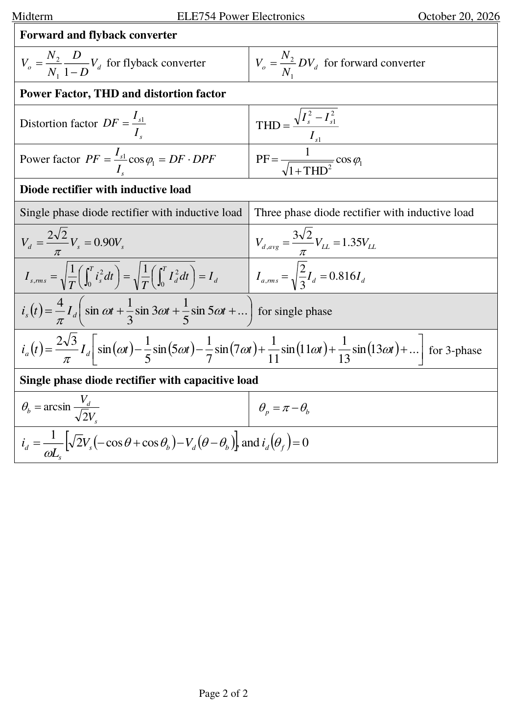
- Divide by $T_s$: $$\boxed{V_o = \frac{N_2}{N_1}\frac{D}{1-D}V_d}$$ On your formula sheet. Drop the turns ratio and it is the buck-boost, $V_o = \frac{D}{1-D}V_d$ (class note arrow on slide 70): a flyback is a buck-boost whose inductor got a second winding (Mohan 10-4-2).
Forward (slides 72 to 73)
- $t_{on}$: same-end dots, so $D_1$ conducts while $T_1$ is on. The secondary puts $\frac{N_2}{N_1}V_d$ in front of an LC filter: $v_L = \frac{N_2}{N_1}V_d - V_o$ (class note: "$D_1$ on").
- $t_{off}$: $D_1$ blocks and $D_2$ freewheels the inductor current: $v_L = -V_o$ ("$D_2$ on"). This is a buck converter whose input is $\frac{N_2}{N_1}V_d$.
- Volt-sec balance on L: $$\left(\frac{N_2}{N_1}V_d - V_o\right)t_{on} = V_o\,t_{off} \;\Rightarrow\; \boxed{V_o = \frac{N_2}{N_1}DV_d}$$ On your formula sheet. The turns ratio scales the buck result (class note: "turns ratio").
Class note on slide 72: an ideal transformer stores no energy. So the forward needs the output inductor to store it, exactly like the buck. A real core does build up magnetising current during $t_{on}$, and it must be brought back to zero every period or the core saturates. The usual fix is a third (reset) winding with a diode back to $V_d$ (Mohan 10-4-3). With $N_3 = N_1$ that limits $D \le 0.5$ and the switch blocks $2V_d$. This is not on the slides or the sheet; know it as the reason, not as a formula you'll be asked to derive.
A real isolated supply (slide 74)
The practical design: ac input, a diode rectifier, a dc-link capacitor, then the isolated dc-dc converter, with a controller sensing the output. Class notes on slide 74: "ac input with diode rectifier", optionally a PFC (power factor correction) or APF (active power filter) stage, an analog power controller, efficiency 96% to 98%, and about 75 W/in³ (the slide asks for more than 50 W/in³). Its features: isolation, a wide input range, multiple outputs, but low utilisation of the transformer. Drawing exactly this chain with a flyback was last year's midterm Q4.1 (8%).
| Flyback | Forward | |
|---|---|---|
| Dots | opposite ends | same end |
| Output diode conducts | during $t_{off}$ | $D_1$ during $t_{on}$, $D_2$ during $t_{off}$ |
| Energy stored in | the transformer (coupled inductor) | the output L |
| $V_o$ (on the sheet) | (N2/N1)·D/(1−D)·Vd | (N2/N1)·D·Vd |
| Parent converter | buck-boost | buck |
| Switch stress (not on the sheet) | Vd + (N1/N2)Vo | 2Vd with a reset winding N3 = N1 |
Flyback and forward bench
Set $V_d$, the turns ratio and either $V_o$ or D. The scope shows the gate, the switch voltage $v_T$ (its peak is the stress) and the currents. Midterm Q4.2 is the first preset; it gives no $L_m$ or $f_s$, so the bench assumes 100 µH and 100 kHz, which keeps it in CCM as the question says.
A flyback runs from a 170 V link with $N_1 : N_2 = 10 : 1$ and must give $V_o = 12$ V in CCM. What duty cycle?
$\frac{D}{1-D} = \frac{N_1}{N_2}\frac{V_o}{V_d} = 10\times\frac{12}{170} = 0.7059$, so $D = \frac{0.7059}{1.7059} = 0.4138$. 0.7059 is the forward-converter answer (or $\frac{D}{1-D}$ left unsolved). 0.0706 is $V_o/V_d$, a buck with no transformer, and 0.0659 is the buck-boost with the turns ratio left out.
Same flyback (170 V, 10 : 1, 12 V). What voltage must the MOSFET block while it is off?
During $t_{off}$, $D_1$ clamps $v_2 = -V_o$, which reflects to $v_1 = -\frac{N_1}{N_2}V_o = -120$ V. So $v_T = V_d - v_1 = 170 + 120 = 290$ V (slide 71). A real MOSFET also sees a leakage-inductance spike on top, which the lecture assumes away. Load the preset "170 V, 10:1, 12 V" and read $v_T$ on the scope.
The dc motor in four equations
A dc motor gives easy speed control over 0.1 W to 1000 kW (trains, elevators, steel mills). Its drawbacks are cost and a commutator that needs maintenance; class note: that's the brushed motor, and the brushless dc motor replaces the commutator with a power converter. The field circuit ($R_f$, $L_f$) sets the flux $\Phi$; with a permanent magnet there is no field circuit at all (class note "PM"). The armature circuit is $R_a$, $L_a$ and a back emf $E_a$.
- Back emf: $E_a = K_a\Phi\,\omega_m$, with $\omega_m$ in rad/s ($n$ rpm $\times\frac{2\pi}{60}$).
- Torque: $T_e = K_a\Phi\,I_a$. Same constant, so $K_a\Phi$ is in V·s/rad and also N·m/A.
- Steady state (class note: no $L_a$, $L_f$): $V_t = R_aI_a + E_a$, and with $P_{rot} = 0$, $T_e = T_m = T_L$.
- Energy conversion: $E_aI_a = T_e\,\omega_m$. Both sides are $K_a\Phi\,\omega_mI_a$.
None of the motor equations is on the F2026 sheet: not $E_a = K_a\Phi\omega_m$, not $T_e = K_a\Phi I_a$, not the speed-torque line. Carry them in your head. The sheet does give the chopper current formulas you combine them with.
Speed-torque line (slides 78 to 79)
- Start from the steady-state armature equation: $V_t = R_aI_a + E_a$.
- Replace each motor quantity: $I_a = \frac{T_e}{K_a\Phi}$ and $E_a = K_a\Phi\,\omega_m$: $$V_t = \frac{R_a}{K_a\Phi}T_e + K_a\Phi\,\omega_m$$
- Solve for speed: $$\boxed{\omega_m = \frac{V_t}{K_a\Phi} - \frac{R_a}{(K_a\Phi)^2}T_e}$$ A straight line: no-load speed $\omega_{m0} = \frac{V_t}{K_a\Phi}$ at $T_e = 0$, and a small droop $\Delta\omega_m = \frac{R_a}{(K_a\Phi)^2}T_e$. Changing $V_t$ moves the intercept only, so the lines stay parallel (slide 79). Usually $V_t \le V_{t,rated}$ to protect the insulation, so $\omega_m \le \omega_{m,rated}$.
The lecture Example's motor ($R_a = 0.8\ \Omega$, $K_a\Phi = 0.9$ V·s/rad) with a fan-type load drawn through the Example's operating point. Grey lines: 150, 100 and 50 V.
Starting (slides 80 to 82)
At $t = 0$ the motor isn't turning, so $E_a = K_a\Phi\cdot0 = 0$ and only $R_a$ limits the current: $I_{start} = \frac{V_t}{R_a}$. For the lecture's motor ($R_a = 0.8\ \Omega$) on 150 V that is 187.5 A. $L_a$ slows the rise, but the peak $i_{a,peak}$ is still very high. As the speed builds, $E_a$ rises and $I_a = \frac{V_t - E_a}{R_a}$ falls to the load value. The fixes: ramp $V_t$ up with an adjustable slope (slide 82, the µP ramp function on slide 102), or limit $I_a$ with a current loop (slide 104). Speed itself is controlled through current: $J\frac{d\omega_m}{dt} = T_e - T_L$ and $T_e = K_a\Phi I_a$ (slide 80).
A dc motor with $V_t = 220$ V, $R_a = 0.5\ \Omega$ and $K_a\Phi = 1.2$ V·s/rad drives $T_L = 24$ N·m in steady state. What is $\omega_m$?
$I_a = T_L/K_a\Phi = 24/1.2 = 20$ A, $E_a = V_t - R_aI_a = 220 - 10 = 210$ V, $\omega_m = E_a/K_a\Phi = 175$ rad/s (1671 rpm). From the line: $\frac{220}{1.2} - \frac{0.5}{1.44}\times24 = 183.3 - 8.3 = 175$ rad/s. 183.3 is the no-load speed $\omega_{m0}$, which ignores the droop.
Converters for dc motors: one, two, four quadrants
Plot the converter's output on the $V_t$-$I_a$ plane. Since $E_a \approx V_t$ in sign, the sign of $V_t$ is the direction of rotation, and since $T_e = K_a\Phi I_a$, the sign of $I_a$ is the direction of torque. One-quadrant chopper (slide 83): $V_t > 0$, $I_a > 0$, power only from $V_d$ to the motor, no braking torque, slow dynamic response. Two-quadrant (slide 84): $V_t > 0$, $I_a = \pm$, so it can brake (class note: motor running in one direction). Full bridge (slide 85): $V_t = \pm$ and $I_a = \pm$, all four quadrants. Braking quadrants (II and IV) send energy back to the source.
A dc motor is turning forward (CW) and must slow down fast, using braking torque rather than just coasting. Which converters can do it?
Braking torque means $T_e = K_a\Phi I_a < 0$, so $I_a$ must reverse while the motor still turns CW ($E_a > 0$, so $V_t > 0$): quadrant IV. The two-quadrant chopper reaches it through $T_2$ and $D_2$, the full bridge too. The one-quadrant chopper can only lower D; $I_a$ falls to zero and the motor coasts on its load (slow dynamic response, slide 83). $V_t < 0$ is needed only to run or brake the other way.
Full bridge (H-bridge), slide 85
Two legs: A ($T_1$ top, $T_4$ bottom) and B ($T_3$ top, $T_2$ bottom), each switch with an antiparallel diode, the motor between A and B: $v_t = v_{AB} = v_{AN} - v_{BN}$. Class notes: $T_1$ and $T_4$ are complementary, $T_3$ and $T_2$ are complementary (dead time neglected), so you only need signals for $T_1$ and $T_3$, usually at the same frequency. The paths below are for $i_a > 0$ (slides 88 and 89).
Bipolar PWM (slide 86)
- Class note: $T_1$ and $T_2$ share one signal, $T_3$ and $T_4$ get its inverse. So $v_{AB}$ jumps straight between $+V_d$ (during $t_{on}$ of $T_1$) and $-V_d$ (during $t_{off}$): a $2V_d$ step every switching.
- Average (Area A1 minus Area A2): $$V_{o,avg} = \frac{V_dt_{on} - V_dt_{off}}{T_s} \;\Rightarrow\; \boxed{V_o = (2D_1 - 1)V_d}, \quad D_1 = \frac{t_{on}}{T_s}\text{ of } T_1$$ $D_1 = 0.5$ gives zero; below 0.5 the average is negative. With $i_a > 0$, when $T_1$ and $T_2$ turn off the current flows on through $D_4$ and $D_3$ into $V_d$ against $-V_d$: fast decay, large ripple current, large ripple torque, more noise.
Unipolar PWM (slide 87)
- Each leg gets its own signal. $T_2$ gets $T_1$'s signal (same $t_{on}$) shifted by $T_s/2$ (class note "shift by $T_s/2$"); $T_4$ and $T_3$ get the inverses. Now $v_{AB}$ steps between $+V_d$ and 0 when the average is positive, and between 0 and $-V_d$ when it is negative (class notes on slide 87).
- The zero states short the motor through the top pair ($T_1$, $D_3$) or the bottom pair ($T_2$, $D_4$): $v_t = 0$, so the current decays only against $R_a$ and $E_a$: slow decay, small ripple current, small ripple torque.
- There are two pulses per period, each $\frac{t_{on} - t_{off}}{2}$ wide: $$V_{o,avg} = \frac{V_d}{T_s}\cdot\frac{t_{on} - t_{off}}{2}\times2 \;\Rightarrow\; \boxed{V_o = (2D_1 - 1)V_d}$$ Same average as bipolar. The ripple repeats twice per period: the effective switching frequency is doubled, $f_{ripple} = 2f_s$ (circled in class).
The slide writes $V_{o,avg} = \frac{V_d}{T_s}\left(\frac{t_{on} + t_{off}}{2}\right)\times2$. With $t_{on} + t_{off} = T_s$ that would give $V_d$ for every $D_1$. The pulse width marked on the same slide's $v_{AB}$ is $\frac{t_{on} - t_{off}}{2}$, and that is what gives the slide's own result $(2D_1 - 1)V_d$. On the exam, write the minus sign.
Bipolar against unipolar
| Bipolar | Unipolar | |
|---|---|---|
| Gate signals | $T_1$,$T_2$ one signal; $T_3$,$T_4$ its inverse | leg A and leg B each their own, B shifted by $T_s/2$ |
| $v_{AB}$ levels | $+V_d$, $-V_d$ | $+V_d$, 0 (or 0, $-V_d$) |
| Average | $(2D_1 - 1)V_d$ | $(2D_1 - 1)V_d$ |
| Freewheeling | fast decay (diodes to $V_d$) | slow decay ($v_t = 0$) |
| Ripple current, torque, noise | large | small |
| Ripple frequency | $f_s$ | $2f_s$ |
$V_o = (2D_1 - 1)V_d$, the bipolar/unipolar differences and the quadrant labels are not on the F2026 sheet. Slide 85 also labels the four-quadrant chart "Output of two-quadrant chopper", a copy-paste slip; the chart is the full bridge's.
For large motors (class note: up to about 2 MW) the converter is a three-phase thyristor rectifier instead (slide 90): $I_a > 0$, $V_t = \pm$. Two of them back to back give four quadrants, with reactors $L_1$, $L_2$ to limit the circulating current between the bridges (slide 91). Thyristor rectifiers are the Oct 6 lecture.
Slides 92 to 95 then work a full example of a one-quadrant chopper driving a motor. It is your worked problem in section 08, with the past exam.
Drive a dc motor yourself
Pick a converter, set the motor's back emf $E_a$ (the speed sets it) and the duty cycle. The top trace is the carrier and control signal, then the gate signals, the terminal voltage with the device conducting in each interval, and the armature current. The full bridge uses a triangle carrier (centre aligned, as slide 96 recommends); slides 86 and 87 draw the same pulses edge aligned, with the same averages and ripple frequency.
The four quadrant presets are one motor ($R_a = 0.5\ \Omega$, $L_a = 2$ mH, $K_a\Phi = 1.2$ V·s/rad) on a 300 V full bridge: $|I_{a,avg}| = 20$ A in each.
A full bridge runs from $V_d = 300$ V. What $D_1$ (duty cycle of $T_1$) gives an average terminal voltage of $-90$ V?
$(2D_1 - 1)\times300 = -90 \Rightarrow 2D_1 - 1 = -0.3 \Rightarrow D_1 = 0.35$. Same answer for bipolar and unipolar. 0.65 gives +90 V. Reversing $V_t$ by moving $D_1$ below 0.5 is exactly what makes the full bridge four-quadrant.
The same full bridge switches at $f_s = 5$ kHz with unipolar PWM. At what frequency does the armature current ripple repeat?
Unipolar PWM puts two $v_{AB}$ pulses in every switching period, so the current ripples at $2f_s = 10$ kHz ("effective switching frequency is doubled", slide 87). Bipolar ripples at $f_s$. Switch the bench between FB bipolar and FB unipolar and count the current peaks.
Gating signals and µP control
Yellow: the control level. Cyan: the carrier. Gate $v_{G1}$ is high while control is above the carrier, so $D = v_c/\hat V$. $v_{G2}$ is the complementary signal for a 2Q leg, with the dead time drawn much wider than real so you can see it.
Analog (slide 96): a comparator, control wave on +, carrier on − (class note: a 555 timer can make the carrier). Simple and cheap, but sensitive to noise. A sawtooth carrier gives edge-aligned pulses: for switch-mode supplies, 1Q and 2Q choppers, flyback and forward. A triangle gives centre-aligned pulses: for three-phase and full-bridge converters. Complementary pairs get a dead time, as in section 01.
Digital (slides 97 to 98): a counter counts from 0 up to the period register and resets; a digital comparator holds the output high while the count is at or below the compare register (class note: the buffer register holds the "control waveform"). So $$D = \frac{[\text{Compare}] + 1}{[\text{Period}] + 1}, \qquad f_{sw} = \frac{f_{counter}}{[\text{Period}] + 1}$$ Slide 98: $\frac{3262 + 1}{4659 + 1} = 0.7$ and $\frac{10\text{ MHz}}{4660} = 2.146$ kHz. Stable and noise-robust and it frees the CPU, but needs extra hardware and a fast counter.
It marks the top of the counter as "0x1234 = 4659d". In fact 0x1234 = 4660 and 0x1233 = 4659, and the staircase on the same slide tops out at 0x1233. The period register holds 0x1233 = 4659, and the slide's arithmetic (4659 + 1 = 4660) is right. Convert hex carefully on the exam: 0x0CBE = 12×256 + 11×16 + 14 = 3262.
µP control of the drive (slides 101 to 104): open loop, the µP generates the gate signals and ramps the real duty cycle D toward the host PC's reference $D^\ast$ to limit the starting current; the delay time sets the slope. Closed loop uses two loops: an inner current loop (current sensed with a shunt resistor or Hall-effect sensor, then A/D) controls $I_a$, which is torque; an outer speed loop (tachometer or encoder) makes the current reference $I_a^\ast$. Clamping $I_a^\ast$ limits the starting current.
A digital PWM block has a 10 MHz counter. You need $f_{sw} = 20$ kHz and $D = 0.35$. What goes in the period and compare registers?
$[\text{Period}] + 1 = \frac{10\text{ MHz}}{20\text{ kHz}} = 500$, so Period = 499 (0x01F3). $[\text{Compare}] + 1 = 0.35\times500 = 175$, so Compare = 174 (0x00AE). 500 and 175 forget the +1 on both; Compare 325 gives the complement, $D = 0.652$.
Software PWM (slides 99 to 100). A free-running counter TCNT (wraps at 0xFFFF = 65535) and an output-compare register OC1. Each interrupt loads OC1 = [TCNT] + TIME_HIGH after a rising edge, or [TCNT] + TIME_LO after a falling edge. Less hardware, but every edge costs CPU time, the interrupt latency makes the pulses imprecise, and very narrow or very wide pulses can be lost. Class note: only for low $f_{sw}$.
Ramp in the ISR (slide 103). If $D_{new} > D_{old}$: $D_{old} = D_{old} + \Delta D$, call conversion (load the compare register), run other functions, repeat until $D_{new} = D_{old}$. The mirror branch subtracts $\Delta D$. Slide 102's answers: adjust the slope with the delay time; track $D^\ast$ by reading it from the host PC inside the ramp loop.
Switching modes (slides 88 to 89). Bipolar uses "normal" ($T_1$ $T_2$ or $T_3$ $T_4$) and "fast decay" (diode pairs back into $V_d$) modes. Unipolar adds "slow decay" with $v_t = 0$. The full-bridge circuit in section 05 steps through the $i_a > 0$ cases.
Sensors (class note on slide 104). Voltage: a divider. Current: a shunt resistor or Hall-effect sensor. Speed: a tachometer or encoder. The speed reference comes from a PLC or PC.
F2025 midterm Q4 and the motor Example
Work it like the real thing: (this year's, the one you'll get on Oct 20), try each part on paper in your notes, then reveal. Last year's Q2 (a one-quadrant chopper with a motor) is worked in Lesson 3; the lecture Example below is the same procedure with the motor equations on top.
F2025 midterm Question 4 (15%): isolated 60 W adapter, about 12 min
A diode rectifier and a flyback converter form an isolated 60 W adapter. Input: single-phase 110 V ac. Output: 5 V dc. The two converters are connected by a dc-link capacitor.
Draw it in your notes first, then compare.
- What earns the marks: four-diode bridge from the 110 V ac source; the dc-link capacitor across the bridge output; the primary winding in series with the MOSFET across the link (MOSFET to the negative rail); transformer dots on opposite ends; secondary diode pointing to the output +, output capacitor, 5 V terminals; no wire from the primary side to the secondary side (isolation). The posted solution draws exactly this.
- Formula sheet, flyback: $V_o = \frac{N_2}{N_1}\frac{D}{1-D}V_d$ with $V_d = 150$ V, $V_o = 5$ V, $\frac{N_2}{N_1} = \frac{1}{4}$.
- $$\frac{D}{1-D} = \frac{N_1}{N_2}\frac{V_o}{V_d} = 4\times\frac{5}{150} = 0.1333 \;\Rightarrow\; D = \frac{0.1333}{1.1333}$$
- D = 0.1176 (solution: 0.1176). Worth knowing too: the MOSFET blocks $150 + 4\times5 = 170$ V, the load current is $60/5 = 12$ A, and the link supplies $60/150 = 0.4$ A on average.
Lecture Example (slides 92 to 95): one-quadrant chopper and a dc motor, about 15 min
Given: $V_d = 150$ V, $L_a = 0.16$ mH, $R_a = 0.8\ \Omega$, $K_a\Phi = 0.9$ V·s/rad, $f_{sw} = 1$ kHz. The motor drives a mechanical load at $n = 650$ rpm with $D = 0.4$. Find (1) $I_{\max}$ and $I_{\min}$, (2) $T_{e,avg}$, (3) sketch $v_t$, $i_a$ and $T_e$ to scale. Class notes on slide 92: "one quadrant chopper with DC motor", and on the "Find": first determine CCM or DCM.
- Basics: $\tau = L_a/R_a$, $T_s = 1/f_{sw}$, $t_{on} = DT_s$, $E_a = K_a\Phi\omega_m$ with $\omega_m = n\cdot\frac{2\pi}{60}$.
- Assume CCM and compute $I_{\min}$ with the sheet's CCM formula. Class note: $I_{\min} > 0$, CCM; $I_{\min} < 0$, DCM.
- DCM: $I_{\min} = 0$; use the DCM column for $I_{\max}$, then $t_x$, and check $t_x < T_s$.
- $V_{o,avg}$, $I_{o,avg} = \frac{V_{o,avg} - E_a}{R_a}$, then $T_{e,avg} = K_a\Phi I_{o,avg}$ (not on the sheet).
- $\tau = \frac{0.16\text{ mH}}{0.8\ \Omega} = 0.2$ ms, $T_s = 1$ ms, $t_{on} = 0.4$ ms, so $t_{on}/\tau = 2$ and $T_s/\tau = 5$.
- $E_a = K_a\Phi\omega_m = 0.9\times\frac{650\times2\pi}{60} = 0.9\times68.07 = 61.3$ V.
- Assume CCM: $$I_{\min} = \frac{V_d}{R_a}\frac{e^{t_{on}/\tau} - 1}{e^{T_s/\tau} - 1} - \frac{E_a}{R_a} = 187.5\times\frac{e^{2} - 1}{e^{5} - 1} - \frac{61.3}{0.8} = 8.13 - 76.6 = -68.5\text{ A} < 0 \;\Rightarrow\; \text{DCM}$$
- DCM column (class note: "DCM formulas"): $$I_{\max} = \frac{V_d - E_a}{R_a}\left(1 - e^{-t_{on}/\tau}\right) = \frac{150 - 61.3}{0.8}\left(1 - e^{-2}\right)$$ $I_{\max} = 95.9$ A, $I_{\min} = 0$ A
- $$t_x = \tau\ln\left\{e^{t_{on}/\tau}\left[1 + \frac{V_d - E}{E}\left(1 - e^{-t_{on}/\tau}\right)\right]\right\} = 0.2\text{ ms}\times\ln\left\{e^{2}\left[1 + \frac{88.7}{61.3}\left(1 - e^{-2}\right)\right]\right\} = 0.562\text{ ms}$$ Class note: "$t_x < T_s$ (1 ms)". If it came out above $T_s$, the current wouldn't run out and you'd be in CCM after all.
- From $t_x$ to $T_s$ nothing conducts, so $i_a = 0$ and $v_t = E_a$, not 0: $$V_{o,avg} = \frac{t_{on}}{T_s}V_d + \frac{T_s - t_x}{T_s}E = 0.4\times150 + 0.438\times61.3 = 86.8\text{ V}$$
- $I_{o,avg} = \frac{86.8 - 61.3}{0.8} = 31.9$ A, and $T_{e,avg} = K_a\Phi I_{o,avg} = 0.9\times31.9 = $ 28.7 N·m
- $v_t$: 150 V from 0 to 0.4 ms, 0 V from 0.4 to 0.562 ms, 61.3 V from 0.562 to 1 ms, then repeat. $i_a$: rises along an exponential to 95.9 A at 0.4 ms, falls to 0 at 0.562 ms, stays at 0. $T_e = K_a\Phi i_a$ has the same shape: peak $0.9\times95.9 = 86.3$ N·m, average 28.7 N·m.
- Dr. Xu's class sketch on slide 95 redraws $v_t$ on its own and marks its levels: $V_d$ while $T_1$ conducts, 0 while $D_1$ does, and $E_a$ once the current has stopped. The bench's "Example · 1Q" preset draws the same traces.
Full-bridge drive
A full bridge with unipolar PWM runs from $V_d = 300$ V at $f_{sw} = 5$ kHz. It drives a dc motor with $R_a = 0.5\ \Omega$, $L_a = 2$ mH and $K_a\Phi = 1.2$ V·s/rad.
- (a) $D_1$ for an average terminal voltage of +90 V: $(2D_1 - 1)\times300 = 90$, so $D_1 = 0.65$. Same for bipolar.
- (b) At that $D_1$ the motor turns at 636.6 rpm. $\omega_m = 636.6\times\frac{2\pi}{60} = 66.67$ rad/s, $E_a = 1.2\times66.67 = 80$ V, $I_{a,avg} = \frac{90 - 80}{0.5} = 20$ A, $T_{e,avg} = 1.2\times20 = 24$ N·m: quadrant I, CW motoring.
- (c) Brake with $I_{a,avg} = -20$ A at the same speed: $V_t = E_a + R_aI_a = 80 - 10 = 70$ V, so $D_1 = \frac{1 + 70/300}{2} = 0.6167$: quadrant IV, CW braking. The motor converts $E_aI_a = 1600$ W, $R_a$ burns 200 W, and 1400 W goes back into $V_d$.
- (d) Ripple frequency: 10 kHz with unipolar PWM ($2f_{sw}$), 5 kHz with bipolar.
Traps that cost marks
- Putting a two-quadrant chopper into DCM. It is always CCM; a negative $I_{\min}$ from the sheet's formula is the answer, not a mode change.
- In a 1Q chopper in DCM, writing $V_{o,avg} = DV_d$ or $v_t = 0$ in the idle gap. From $t_x$ to $T_s$, $v_t = E_a$.
- Plugging rpm into $E_a = K_a\Phi\omega_m$. Convert: $\omega_m = n\times2\pi/60$.
- Turning the turns ratio upside down. $V_d$ is multiplied by $N_2/N_1$, and in Q4 $N_1$ is the high-voltage (primary) side.
- Using the forward formula for a flyback, or the other way round. Flyback: $\frac{D}{1-D}$; forward: $D$.
- Saying the flyback switch blocks $V_d$. It blocks $V_d + \frac{N_1}{N_2}V_o$.
- Full bridge: $D_1 = 0.5$ gives zero average, not $V_d/2$. $V_o = (2D_1 - 1)V_d$ is not on the sheet.
- Copying slide 87's $(t_{on} + t_{off})/2$. The unipolar pulse is $(t_{on} - t_{off})/2$, two per period, ripple at $2f_s$.
- Motor equations from memory: $E_a = K_a\Phi\omega_m$, $T_e = K_a\Phi I_a$, $V_t = R_aI_a + E_a$. None is on the sheet.
- Mixing up the quadrants. $V_t$ is across, $I_a$ is up (slide 85). II and IV are braking: II is CCW braking ($V_t < 0$, $I_a > 0$), IV is CW braking ($V_t > 0$, $I_a < 0$). A two-quadrant chopper reaches I and IV only.
- PWM registers: both need the +1. $D = \frac{C + 1}{P + 1}$, $f_{sw} = \frac{f_{counter}}{P + 1}$.
- No units, no marks: the midterm cover says "Marks will be lost if there is no appropriate units."
Drill it in chat
Go back to the chat and say "quiz me on dc motor drives". You get one question at a time, and I'll fix exactly where your reasoning breaks.
Then the grill
grill.pierrek.ca · ELE754 sections "L4: Two-quadrant chopper, flyback & forward" (11 questions), "L4: DC motor drives & full bridge" (12), "L4: Gating signals & µP control" (7), and "Formula sheet (F2026): find it, use it, know what's missing" (10).