Why switch at all?
Say you need 12 V at 20 A from a 48 V bus. A linear regulator drops the extra 36 V across a transistor carrying the full 20 A. That is 720 W of heat to deliver 240 W.
A switch is either fully on, with $v_{DS} \approx 0$ so $P = v_{DS}\,i_d \approx 0$, or fully off, with $i_d \approx 0$ so again $P \approx 0$. It never sits in the active region, so in the ideal model it wastes nothing. The catch is that a switch can only make pulses. So every dc-dc converter in this course is two blocks in series: a chopper that makes pulses and a low-pass filter (L and C) that keeps the average. That is Dr. Xu's margin note on slide 14.
The buck's parts
- $T_1$, a MOSFET: fully on or fully off, never in the active region.
- $D_1$, the freewheeling diode: when $T_1$ opens, the inductor current can't just stop, so $D_1$ gives it a path.
- L and C: the low-pass filter. High switching frequency is what lets them be small.
- R: the load.
Ideal switches ($V_{DS,on} = 0$, $V_{D1,on} = 0$), and $C = \infty$ so $V_o$ is constant with no ripple. The ripple section later drops the second assumption.
The two states of a buck
A converter in steady state just alternates between two circuits. Flip the switch and watch where the current goes.
On: the switch node sits at $V_d$. The inductor has $V_d$ on its left and $V_o$ (held by C) on its right, so $v_L = V_d - V_o > 0$: $i_L$ ramps up and L stores energy.
Off: the inductor current keeps flowing and forces $D_1$ on, so the switch node drops to 0 and $v_L = -V_o$: $i_L$ ramps down and L hands its energy to C and R.
$v_L$ is constant within each interval and $v_L = L\,\frac{di_L}{dt}$, so the slope $\frac{di_L}{dt} = \frac{v_L}{L}$ is constant. Every buck and boost current is built from straight ramps: $\Delta i_L = \frac{v_L}{L}\Delta t$ (slide 22, first key equation).
$T_1$ has just turned off in a buck converter running in CCM. What is $v_L$?
With $T_1$ open, $D_1$ carries $i_L$ and clamps the switch node to 0 V. The inductor sees 0 on the left and $V_o$ on the right, so $v_L = 0 - V_o = -V_o$. A negative $v_L$ is exactly what makes $i_L$ ramp down.
The one rule: volt-second balance
This is the move you'll make in every converter question. Step through it.
- Inductor law over one period: $$v_L = L\frac{di_L}{dt} \;\Rightarrow\; i_L(T_s) - i_L(0) = \frac{1}{L}\int_0^{T_s} v_L\,dt$$
- Steady state means $i_L$ ends each period exactly where it started, so $$\int_0^{T_s} v_L\,dt = 0 \quad\Longleftrightarrow\quad \text{Area } A_1 = \text{Area } A_2$$ $A_1$ is the positive (red) area of $v_L$, $A_2$ the negative (yellow) one, as on slide 16. Dr. Xu's wording: an ideal inductor has no dc voltage drop.
- Buck: $v_L = V_d - V_o$ during $t_{on}$ and $v_L = -V_o$ during $t_{off}$: $$(V_d - V_o)\,t_{on} = V_o\,t_{off} = V_o(T_s - t_{on})$$
- Divide by $T_s$ and use $D = t_{on}/T_s$: $$(V_d - V_o)D = V_o(1-D) \;\Rightarrow\; \boxed{V_o = DV_d}$$ Since $0 \le D \le 1$, $V_o \le V_d$: a step-down converter.
- Currents: KCL at the output node gives $i_L = i_C + i_o$. A capacitor in steady state carries zero average current, so $$\boxed{I_L = I_o}$$ Class note: "only for buck converter". The boost is different.
The same three moves (write $v_L$ in each interval, set the areas equal, solve) give you the boost, the flyback and the forward converter. Learn the moves, not the four formulas.
A buck in CCM must give 5 V from a 24 V input. What duty cycle?
$D = V_o/V_d = 5/24 = 0.208$. "Areas equal" doesn't mean equal times: $A_1 = 19\text{ V}\times 0.208T_s$ and $A_2 = 5\text{ V}\times 0.792T_s$, both $3.96T_s$. A large voltage for a short time balances a small voltage for a long time.
Run the converter yourself
Everything here is computed with the lecture's formulas, so it doubles as an answer checker for past exams. Load a preset, then break things: lighten the load until it drops into DCM, shrink L, slow the clock.
CCM, critical mode, DCM
Make the load lighter and the average $I_L$ drops. The ripple doesn't care: $\Delta I_L = \frac{V_d - V_o}{L}DT_s$ has no load in it. So the triangle slides down, and eventually its bottom hits zero. $D_1$ can't conduct backwards, so $i_L$ can't go negative: it sits at zero for part of each period. That is discontinuous current mode.
The boundary (critical mode)
At the boundary the triangle just touches zero, so its average is half its peak (slide 18):
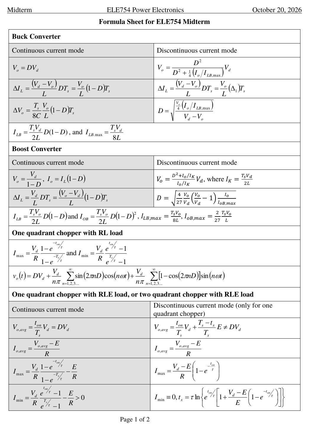
$$I_{LB} = \tfrac{1}{2}i_{L,peak} = \tfrac{1}{2}\Delta I_L = \frac{1}{2L}(V_d - V_o)DT_s = \frac{T_sV_d}{2L}D(1-D)$$As a function of D this is a parabola with its peak at $D = 0.5$: $I_{LB,\max} = \frac{T_sV_d}{8L}$ (slide 19). In class Dr. Xu wrote the critical condition as $I_L = I_{LB}$, and noted $\Delta I_L = 2I_{LB}$.
- Find the load current: $I_o = V_o/R$ (or $P/V_o$). Buck: $I_L = I_o$.
- Assume CCM: $D = V_o/V_d$.
- Compute $I_{LB} = \frac{T_sV_d}{2L}D(1-D)$ at that D.
- $I_L > I_{LB}$: CCM, done. $I_L = I_{LB}$: critical. $I_L < I_{LB}$: DCM, so throw away the CCM duty cycle and use the DCM formula.
Deriving the DCM formulas (slides 20 to 21)
- DCM has three intervals: $DT_s$ ($T_1$ on, $v_L = V_d - V_o$), $\Delta_1T_s$ ($D_1$ on, $v_L = -V_o$), and the rest (both off, $i_L = 0$, so $v_L = 0$).
- Volt-sec balance over the period: $$(V_d - V_o)DT_s = V_o\Delta_1T_s \;\Rightarrow\; V_o = \frac{D}{D+\Delta_1}V_d \quad (1)$$
- The peak from the falling ramp: $i_{L,peak} = \frac{V_o}{L}\Delta_1T_s$. The load gets the average of the triangle: $I_o = \tfrac{1}{2}i_{L,peak}(D + \Delta_1)$.
- Use (1) to swap $D + \Delta_1 = DV_d/V_o$, and note $\frac{T_sV_d}{2L} = 4I_{LB,\max}$: $$I_o = \frac{1}{2}\cdot\frac{V_o\Delta_1T_s}{L}\cdot\frac{DV_d}{V_o} = 4I_{LB,\max}D\Delta_1 \;\Rightarrow\; \Delta_1 = \frac{I_o}{4I_{LB,\max}D} \quad (2)$$
- (2) into (1): $$V_o = \frac{D^2}{D^2 + \frac{1}{4}\left(I_o/I_{LB,\max}\right)}V_d$$
- When a controller holds $V_o$ (the usual exam setup), solve for D: $$D = \sqrt{\frac{\frac{V_o}{4}\left(I_o/I_{LB,\max}\right)}{V_d - V_o}}$$ Both boxed formulas are on the formula sheet. Steps 2 to 4 are what you need to rebuild them if you blank.
What DCM does to the output
With D fixed, $\frac{V_o}{V_d} = \frac{D}{D+\Delta_1}$ and $\Delta_1 < 1 - D$, so $V_o/V_d > D$: the output climbs above $DV_d$. Those are the curves Dr. Xu sketched above the CCM line on slide 21. With a controller it shows up the other way round: the same $V_o$ needs a smaller D. Example I part (4) needed 0.2454 instead of 0.32. On the bench, pick Fixed D and raise R to see the climb.
Example I with $R = 100\ \Omega$: $V_d = 150$ V, $V_o = 48$ V, so $I_L = 0.48$ A, and $I_{LB} = 0.816$ A at $D = 0.32$. What now?
$0.48 < 0.816$, so DCM. The controller still holds 48 V, so D changes: $I_{LB,\max} = \frac{T_sV_d}{8L} = 0.9375$ A and $D = \sqrt{\frac{12\times(0.48/0.9375)}{102}} = 0.2454$. If D had stayed at 0.32 the output would rise above 48 V, not fall. Load preset "Example I, R = 100 Ω" on the bench to see it.
A buck runs at a fixed D with no feedback. The load gets lighter until it's in DCM. What happens to $V_o/V_d$?
From $V_o/V_d = D/(D + \Delta_1)$ with $\Delta_1 < 1 - D$. As $I_o \to 0$, $\Delta_1 \to 0$ and $V_o \to V_d$. This is also one reason a buck needs a minimum (dummy) load: F2025 midterm Q1.4.
Output ripple
Now drop the $C = \infty$ assumption. Slide 23 splits the inductor current: the dc part goes to the load, the ripple part goes into the capacitor. So $i_C = i_L - I_o$, a triangle that swings $\pm\Delta I_L/2$ around zero.
- While $i_C > 0$ the capacitor charges and $v_o$ rises. That positive piece is a triangle with base $T_s/2$ and height $\Delta I_L/2$: $$\Delta Q = \frac{1}{2}\cdot\frac{T_s}{2}\cdot\frac{\Delta I_L}{2} = \frac{\Delta I_L\,T_s}{8}$$
- $$\Delta V_o = \frac{\Delta Q}{C} = \frac{\Delta I_L\,T_s}{8C} \quad (1)$$
- The CCM ripple from the $t_{off}$ interval: $\Delta I_L = \frac{V_o}{L}(1-D)T_s$ (2)
- (2) into (1) gives the formula-sheet version: $$\Delta V_o = \frac{T_s}{8C}\frac{V_o}{L}(1-D)T_s$$ and with $f_c = \frac{1}{2\pi\sqrt{LC}}$, slide 24's form: $$\frac{\Delta V_o}{V_o} = \frac{\pi^2}{2}(1-D)\left(\frac{f_c}{f_s}\right)^2$$
Example I prints its answer as "4.5 mV". The formula gives the ratio $\Delta V_o/V_o \approx 4.5\times10^{-3}$, so the ripple is about $0.0045\times48 \approx 0.22$ V. Dr. Xu flagged this in class.
Making the ripple smaller (slide 25)
- Lower $f_c$ with a bigger L or C: works, but the converter gets bigger.
- Raise $f_s$: ripple falls with $1/f_s^2$, but switching loss goes up and efficiency goes down.
- Cut switching loss with low-loss devices (MOSFETs; from class, SiC and GaN MOSFETs) or soft switching (ZVS, ZCS).
- Rule of thumb: $f_s \approx (10 \text{ to } 100)f_c$ keeps $\Delta V_o/V_o$ under 1%.
Ripple in DCM
In DCM the triangle isn't centred on $I_o$, so use the charge area directly: the part of $i_L$ above $I_o$ is a smaller triangle, $$\text{Area} = \frac{1}{2}\frac{(i_{L,pk} - I_o)^2}{i_{L,pk}}(D + \Delta_1)T_s, \qquad C = \frac{\text{Area}}{\Delta V}$$ That is the Quiz 1 Version A method, worked in the Past exam section.
A buck is in CCM. You want to halve $\Delta V_o$ by changing only the switching frequency. Multiply $f_s$ by:
$\Delta V_o \propto T_s^2 = 1/f_s^2$ (one $T_s$ from $\Delta I_L$, one from the charge time). Halving it needs $f_s^2$ to double, so $f_s \times \sqrt{2}$.
Boost: same rule, rearranged
Move the inductor to the input, put the switch to ground, and send the diode to the output. Slide 30's margin notes call the buck a voltage chopper (it chops the voltage; the current into the load is smooth) and the boost a current chopper (the output gets current in pulses).
- $t_{on}$: $T_1$ shorts the inductor across the source, so $v_L = V_d$ and $i_L$ ramps up. $D_1$ is reverse biased by $V_o$, so the load runs on C alone.
- $t_{off}$: $T_1$ opens and the inductor current pushes through $D_1$ into the output: $v_L = V_d - V_o < 0$, so $i_L$ ramps down.
- Volt-sec balance: $$V_d\,t_{on} = (V_o - V_d)\,t_{off} \;\Rightarrow\; \boxed{V_o = \frac{V_d}{1-D}} \ge V_d$$
- Currents (slide 32): the diode passes $i_L$ only during $t_{off}$, so $$I_o = I_D = \frac{t_{off}}{T_s}I_L \;\Rightarrow\; \boxed{I_o = (1-D)I_L}$$ Same as power balance $V_dI_L = V_oI_o$. The inductor carries more current than the load. Using $I_L = I_o$ here is the buck habit, and it's wrong.
Boundary and DCM (slides 33 to 36, F2026 formula sheet)
Same idea as the buck, but there are two boundary currents, one for each side of the converter: $$I_{LB} = \frac{T_sV_o}{2L}D(1-D), \qquad I_{OB} = \frac{T_sV_o}{2L}D(1-D)^2$$ Compare like with like: inductor current with $I_{LB}$, or output current with $I_{OB}$. With $V_o$ held constant, $I_{LB}$ peaks at $D = 0.5$ ($I_{LB,\max} = \frac{T_sV_o}{8L}$) and $I_{OB}$ peaks at $D = 1/3$ ($I_{OB,\max} = \frac{2}{27}\frac{T_sV_o}{L}$). All four are on this year's sheet.
In DCM, volt-sec balance gives $V_o = \frac{D + \Delta_1}{\Delta_1}V_d$. The load gets the diode's triangle, $I_o = \tfrac{1}{2}i_{L,pk}\Delta_1$ with $i_{L,pk} = \frac{V_d}{L}DT_s$, so $\Delta_1 = \frac{I_o}{I_KD}$ where $I_K = \frac{T_sV_d}{2L}$. Put that back in and you get the F2026 sheet's row: $$V_o = \frac{D^2 + I_o/I_K}{I_o/I_K}V_d$$ With $V_o$ held by a controller, the sheet's duty cycle is $$D = \sqrt{\frac{4}{27}\frac{V_o}{V_d}\left(\frac{V_o}{V_d} - 1\right)\frac{I_o}{I_{OB,\max}}}, \qquad I_{OB,\max} = \frac{2}{27}\frac{T_sV_o}{L}$$
The F2026 sheet writes $I_{OB,\max}$ with $V_o$ and has an extra $\frac{V_o}{V_d}$ in the D formula. Slide 36 writes $I_{OB,\max} = \frac{2}{27}\frac{T_sV_d}{L}$ (with $V_d$) and leaves that factor out. Each pair gives the same D. Last year's sheet mixed them (the $V_o$ version without the factor), so F2025 solutions built on it come out too small by $\sqrt{V_d/V_o}$.
Simplest route: $D = \sqrt{\left(\frac{V_o}{V_d} - 1\right)\frac{I_o}{I_K}}$, which is the sheet's $V_o$ row solved for D. Then check in three lines: $i_{L,pk} = \frac{V_d}{L}DT_s$, $\Delta_1 = \frac{V_dD}{V_o - V_d}$, and $I_o = \tfrac{1}{2}i_{L,pk}\Delta_1$ must come out right.
A boost goes from 24 V to 60 V and delivers 1.2 A in CCM. What is the average inductor current?
$D = 1 - 24/60 = 0.6$, so $I_L = I_o/(1-D) = 1.2/0.4 = 3.0$ A. Power check: $24\times3.0 = 60\times1.2 = 72$ W.
Which comparison is a valid boost mode check?
$I_{OB} = (1-D)I_{LB}$, exactly like $I_o = (1-D)I_L$. Pair the output current with the output boundary, or the inductor current with the inductor boundary. Mixing them is off by a factor $(1-D)$.
F2025 midterm, Question 1 (25%)
Work it like the real thing: (this year's, the one you'll get on Oct 20), try each part on paper in your notes, then reveal.
A 240 W buck converter with a voltage-feedback controller has $V_d = 48$ V and $L = 6.8\ \mu$H. The controller adjusts the switching frequency and duty cycle to hold $V_o = V_{ref} = 12$ V. From 24 W to 240 W it always runs in critical mode. Below 24 W the frequency stays at its maximum and only the duty cycle is adjusted.
Try it on paper first. Hint: critical mode means $I_L = I_{LB}$; solve for $T_s$.
- Critical mode: $I_L = I_{LB} = \frac{T_sV_d}{2L}D(1-D) \Rightarrow T_s = \frac{2LI_{LB}}{V_dD(1-D)}$, with $D = \frac{12}{48} = 0.25$ (critical mode still obeys $V_o = DV_d$).
- 24 W: $I_o = I_L = \frac{24}{12} = 2$ A, so $T_s = \frac{2\times6.8\ \mu\text{H}\times2}{48\times0.1875} = 3.022\ \mu$s and $f_s = 330.9$ kHz.
- 240 W: $I_L = 20$ A, so $T_s = 30.22\ \mu$s and $f_s = 33.09$ kHz.
- 33.09 kHz ≤ f_s ≤ 330.9 kHz. Heavier load, lower frequency: critical mode needs $\Delta I_L = 2I_L$, and more ripple needs a longer on-time.
- Full load is critical mode, which sits on the CCM boundary, so the CCM ripple formula holds with $T_s = 30.22\ \mu$s.
- $$\Delta V_o = \frac{T_s}{8C}\frac{V_o}{L}(1-D)T_s \;\Rightarrow\; C = \frac{T_s^2V_o(1-D)}{8L\,\Delta V_o} = \frac{(30.22\ \mu\text{s})^2\times12\times0.75}{8\times6.8\ \mu\text{H}\times0.1\text{ V}}$$
- C = 1511 µF
- $f_s = 330.9$ kHz, where the boundary current is $I_{LB} = 2$ A (that's how the maximum frequency was set).
- $I_L = I_o = \frac{10}{12} = 0.833$ A $< 2$ A, so DCM.
- $I_{LB,\max} = \frac{T_sV_d}{8L} = \frac{3.022\ \mu\text{s}\times48}{8\times6.8\ \mu\text{H}} = 2.667$ A
- $$D = \sqrt{\frac{\frac{V_o}{4}(I_o/I_{LB,\max})}{V_d - V_o}} = \sqrt{\frac{3\times0.3125}{36}} = $$ 0.1614 (CCM would have said 0.25).
- Dr. Xu's answer: the dummy resistor (dummy load) damps the LC resonance. With no load, L and C form an undamped resonant circuit that rings at $f_c$ after any disturbance.
- Worth adding: as $I_o \to 0$ the converter goes deep into DCM, where $V_o \to V_d$ for any fixed D, so D would have to shrink toward zero to regulate. A minimum load keeps regulation possible.
Quiz 1, both versions
Extra if you have time. Skip it to stay under 80 minutes; the grill has more of the same.
Version A: buck, 12 V to 3.3 V, 100 W, 100 kHz
- $I_L = I_o = \frac{100}{3.3} = 30.3$ A. Assume CCM: $D = \frac{3.3}{12} = 0.275$, $T_s = 10\ \mu$s.
- $I_{LB} = \frac{1}{2}\Delta I_L = 10$ A $< I_L$, so CCM holds.
- $L = \frac{V_d - V_o}{\Delta I_L}DT_s = \frac{8.7}{20}\times0.275\times10\ \mu\text{s} = $ 1.196 µH
- $I_L = 5$ A $< I_{LB} = 10$ A, so DCM. To hold 3.3 V: $I_{LB,\max} = \frac{T_sV_d}{8L} = 12.54$ A and $D = \sqrt{\frac{\frac{3.3}{4}(5/12.54)}{8.7}} = 0.1945$.
- $i_{L,pk} = \frac{V_d - V_o}{L}DT_s = 14.14$ A and $\Delta_1 = \frac{I_o}{4I_{LB,\max}D} = 0.5127$.
- The capacitor charges while $i_L > I_o$: a triangle of height $i_{C,pk} = 14.14 - 5 = 9.14$ A. $$\text{Area} = \frac{1}{2}\frac{i_{C,pk}^2}{i_{L,pk}}(D + \Delta_1)T_s = 2.09\times10^{-5}\ \text{A·s}$$
- $C = \frac{\text{Area}}{\Delta V} = \frac{2.09\times10^{-5}}{1\text{ mV}} = $ 0.0209 F
Version B: boost, 12 V to 54 V LED string, 300 mA, 100 kHz
- Assume CCM: $D = 1 - \frac{12}{54} = 0.7778$. $I_o = 0.3$ A, so $I_L = \frac{I_o}{1-D} = 1.35$ A.
- $I_{LB} = \frac{1}{2}\Delta I_L = 1.25$ A $< I_L$, so CCM.
- $\Delta I_L = \frac{V_d}{L}t_{on} \Rightarrow L = \frac{12}{2.5}\times7.778\ \mu\text{s} = $ 37.3 µH
- $I_{L,\max} = I_L + \frac{1}{2}\Delta I_L = 2.6$ A and $I_{L,\min} = 0.1$ A.
- During $t_{off}$ the diode carries $i_L$, so $i_C = i_L - I_o$ starts at $i_{C,pk} = 2.6 - 0.3 = 2.3$ A and falls with the inductor's slope.
- $$\text{Area} = \frac{1}{2}\frac{i_{C,pk}^2}{\Delta I_L}(1-D)T_s = 2.351\times10^{-6}\ \text{A·s}$$
- $C = \frac{\text{Area}}{\Delta V} = $ 235.1 µF (Mohan's shortcut $I_oDT_s/\Delta V$ gives 233 µF, nearly the same)
Traps that cost marks
- Comparing $I_L$ with $I_{LB,\max}$. Use $I_{LB}$ at your actual D; $I_{LB,\max}$ is only the top of the parabola.
- Keeping the CCM duty cycle after finding DCM. Once it's DCM, recompute D (and anything built on it).
- $I_L = I_o$ in a boost. That's the buck. Boost: $I_L = I_o/(1-D)$.
- Mixing boost boundaries: $I_o$ goes with $I_{OB}$, $I_L$ with $I_{LB}$.
- Bringing the capacitor into the mode check. It never decides CCM or DCM.
- Critical mode is not a third set of formulas. It's the edge of CCM: $V_o = DV_d$, $\Delta I_L = 2I_L$, CCM ripple formula.
- Using $V_d$ for $v_L$ during a buck's on-time. It's $V_d - V_o$.
- Boost DCM: use the F2026 sheet's D formula with its own $I_{OB,\max}$ (written with $V_o$), or go through $I_K$. Never pair the sheet's $I_{OB,\max}$ with slide 36's formula. Check with $I_o = \frac{1}{2}i_{L,pk}\Delta_1$.
- No units, no marks: the midterm cover says "Marks will be lost if there is no appropriate units."
Drill it in chat
Go back to the chat and say "quiz me on buck and boost". You get one question at a time, and I'll fix exactly where your reasoning breaks.
Then the grill
grill.pierrek.ca · ELE754 sections "L2: Buck converter" (16 questions) and "L2: Boost converter" (8).